the Creative Commons Attribution 4.0 License.
the Creative Commons Attribution 4.0 License.
 | 23 Oct 2024
Solutions and case studies for thermally driven reactive transport and porosity evolution in geothermal systems (reactive Lauwerier problem)
Einat Aharonov
Piotr Szymczak
Manolis Veveakis
Boaz Lazar
Laura E. Dalton
Subsurface non-isothermal fluid injection is a ubiquitous scenario in energy and water resource applications, which can lead to geochemical disequilibrium and thermally driven solubility changes and reactions. Depending on the nature of the solubility of a mineral, the thermal change can lead to either mineral dissolution or precipitation (due to undersaturation or supersaturation conditions). Here, by considering this thermo-hydro-chemical (THC) scenario and by calculating the temperature-dependent solubility using a non-isothermal solution (the so-called Lauwerier solution), thermally driven reactive transport solutions are derived for a confined aquifer. The coupled solutions, hereafter termed the “reactive Lauwerier problem”, are developed for axisymmetric and Cartesian symmetries and additionally provide the porosity evolution in the aquifer. The solutions are then used to study two common cases: (I) hot CO2-rich water injection into a carbonate aquifer and (II) hot silica-rich water injection into a sandstone aquifer, leading to mineral dissolution and precipitation, respectively. We discuss the timescales of such fluid–rock interactions and the changes in hydraulic system properties. The solutions and findings contribute to the understanding and management of subsurface energy and water resources, such as aquifer thermal energy storage, aquifer storage and recovery and reinjection of used geothermal water. The solutions are also useful for developing and benchmarking complex coupled numerical codes.
Please read the corrigendum first before continuing.
-
Notice on corrigendum
The requested paper has a corresponding corrigendum published. Please read the corrigendum first before downloading the article.
-
Article
(1741 KB)
-
The requested paper has a corresponding corrigendum published. Please read the corrigendum first before downloading the article.
- Article
(1741 KB) - Full-text XML
- Corrigendum
- BibTeX
- EndNote


The recharge or injection of fluids in constrained physical and chemical states in geothermal systems and aquifers is a common phenomenon in both natural and applied systems (Phillips, 2009; Stauffer et al., 2013). In many instances, thermal changes within these systems can shift the system from a state of geochemical equilibrium to disequilibrium and lead to chemical reactions over extensive distances determined by the variations in temperature. These perturbations result from the changes in the solubility of minerals in groundwater, which can become supersaturated or undersaturated in response to thermal changes. These thermally driven reactions cause progressive changes in the rock porosity and hydraulic properties that result from accumulation, removal, or replacement of solid minerals and the accompanied volumetric changes (Phillips, 2009; Woods, 2015). Such processes are responsible for the natural transformations of rocks from diagenesis and metamorphism (Jamtveit and Yardley, 1996; Yardley et al., 2011) to the evolution of aquifers and reservoirs (Andre and Rajaram, 2005; Jones and Xiao, 2006) and melt migration in the Earth's mantle (Aharonov et al., 1995; Kelemen et al., 1995). In applied systems, fluid–rock interactions can significantly impact hydrothermal performance at a timescale of years (Huenges et al., 2013; Pandey et al., 2018).
Depending on the natural solubility of the minerals in the system, an increase in temperature can induce either dissolution or precipitation. This is because mineral solubilities can either increase with temperature (“prograde solubility”) or decrease with it (“retrograde solubility”; Jamtveit and Yardley, 1996; Woods, 2015). Flow and transport commonly influence the state of saturation by continuously introducing thermally disequilibriated fluid, which subsequently becomes geochemically disequilibriated. This occurs because, in many cases, advection serves as the dominant transport mechanism, characterized by a shorter timescale (tA) compared to diffusive heat (tC) or diffusive solute transport (tD). These timescales are represented by , , and , where lA, lC, and lD are characteristic length scales of advection, heat conduction, and ionic diffusion, respectively. Here, uA denotes the characteristic Darcy flux [L T−1], while αb and D are the bulk thermal diffusivity and ionic diffusion coefficient, respectively. The ratio of these timescales defines the thermal Péclet number () and the solute Péclet number (), which are used to characterize the transport regime in these systems. When PeT and Pes are high (i.e., ≫1), advective transport prevails (Ladd and Szymczak, 2021; Nield and Bejan, 2017; Roded et al., 2020).
The overall integrated action of these mechanisms results in a coupled thermo-hydro-chemical (THC) process (Huenges et al., 2013; Pandey et al., 2018; Phillips, 2009; Regenauer-Lieb et al., 2013). The tightly coupled feedbacks in THC processes commonly render them highly nonlinear. Fluid flow and diffusive heat and solute transport induce chemical reactions, which alter the pore structure and its transport properties, leading to further feedback on flow and transport (Chaudhuri et al., 2013; Phillips, 2009; Woods, 2015). Studying these coupled feedback alterations improves the understanding of reactive transport processes taking place in the Earth's upper crust. Specifically, these studies are integral to the sustainable planning and long-term management of water resources (Andre and Rajaram, 2005; Phillips, 2009), geothermal energy systems (on the scale of tens of years; Frick et al., 2011; Huenges et al., 2013; Pandey et al., 2018), and CO2 geo-sequestration (Dávila et al., 2020; Steefel et al., 2013; Tutolo et al., 2015).
In enhanced geothermal systems (EGSs) in particular, channelized dissolution can create a short circuit and reduce the heat exchange between the rock and the fluid. Conversely, precipitation can significantly reduce permeability, leading to reduced production and potentially sealing reservoirs (Huenges et al., 2013; Olasolo et al., 2016; Pandey et al., 2018). Another challenge associated with geothermal utilization is the risk of groundwater contamination, where thermal changes can lead to the leaching of undesired chemical species from the rocks. Specifically, contamination may arise from the reinjection of fluids required to maintain reservoir pressure from aquifer thermal energy storage (ATES) systems that leverage seasonal temperature fluctuations (Bonte et al., 2014; Glassley, 2014; Possemiers et al., 2014). It may also result from substantial injections of hotter or colder water for groundwater management practices, such as aquifer storage and recovery (ASR) (Maliva, 2019; Zheng et al., 2021).
In terms of mineralogy, a range of thermally driven reactions occurs in the previously mentioned systems. Commonly reported precipitates accumulating in geothermal plant piping loops and natural spring deposits include carbonates (e.g., calcite, dolomite, and siderite), sulfates (e.g., gypsum and baryte), and amorphous silica (Glassley, 2014; Huenges et al., 2013). Particularly, geothermal systems composed of sandstones and carbonates are ubiquitous in the Earth's crust and are prone to alterations (Goldscheider et al., 2010; Pandey et al., 2018; Wood and Hewett, 1984). The solubility of silica is proportional to temperature (i.e., prograde solubility), and water pumping or injection can lead to substantial changes in reservoir transmissivity that can affect heat extraction (Pandey et al., 2018; Rawal and Ghassemi, 2014; Taron and Elsworth, 2009). In particular, silica precipitation can occur several orders of magnitude faster than the dissolution of either quartz minerals or amorphous silica (Rimstidt and Barnes, 1980). The exception is the dissolution of unconsolidated amorphous silica sediments (e.g., diatomite). Due to the high specific reactive surface area of the material, these sediments can be intensely dissolved when steam and hot water undersaturated with respect to silica are injected (Bhat and Kovscek, 1998). In contrast to silica, carbonate minerals demonstrate an inverse relation (i.e., retrograde solubility), which is often strong and influenced by CO2 content. Consequently, limestone and dolomite aquifers and reservoirs subjected to geothermal flows, commonly rich in CO2, can evolve at relatively short timescales. Either rapid dissolution or rapid precipitation can occur in such systems depending on conditions (Andre and Rajaram, 2005; Coudrain-Ribstein et al., 1998; Roded et al., 2023).
Investigating the multi-physical systems of THC processes is complex and relies on numerical models facilitated by ongoing advancements in computational capabilities (Kolditz et al., 2016; Pandey et al., 2018; Steefel et al., 2015). Over recent decades, these models have improved the understanding of subsurface processes (Niemi et al., 2017; Regenauer-Lieb et al., 2013; Seigneur et al., 2019; Steefel et al., 2013); however, the validity of such models remains questionable if the results cannot be rigorously tested (Kolditz et al., 2016; Nield and Bejan, 2017). Particularly, analytical solutions allow for the establishment of functional relationships between variables and physical properties and provide robust reliability and accuracy tests for numerical models (Bear and Cheng, 2010; Diersch and Kolditz, 2002; Nield and Bejan, 2017). However, comprehensive testing of multi-coupled THC codes is often mathematically cumbersome and precluded by many different approaches. This limitation arises because existing theoretical solutions focus solely on scenarios related to heat and/or solute transport (Diersch and Kolditz, 2002; Nield and Bejan, 2017; Stauffer et al., 2013; Turcotte and Schubert, 2002) or reactive solute transport (Bear and Cheng, 2010; Nield and Bejan, 2017) and because complete solutions that involve coupled THC processes are scarce (White et al., 2018). To the best of the authors' knowledge, coupled THC solutions are limited to two scenarios: thermally driven reactive front development (Jupp and Woods, 2003, 2004) and thermal and/or solutal convection in a reactive medium (e.g., Rayleigh–Bénard equivalent in a reactive porous medium; Al-Sulaimi, 2015; Corson and Pritchard, 2017). Solutions for fundamental and practical situations in geothermal and groundwater systems, such as non-isothermal injection into a reservoir and consequent matrix modifications, are missing. This is despite the existence of the so-called “Lauwerier solution” (Lauwerier, 1955), which analytically predicts the thermal field resulting from hot (or cold) fluid injection into a thin non-reactive confined layer system. The Lauwerier solution has served as the basis for the development of multiple modified heat transport solutions, accounting for various boundary conditions and system geometries, considering conduction and dispersion, and even accommodating fractured media (Abbasi et al., 2017; Chen and Reddell, 1983; Lin et al., 2019; Shaw-Yang and Hund-Der, 2008; Voigt and Haefner, 1987; Yang et al., 2010; Zhou et al., 2019; Ziagos and Blackwell, 1986; see review in Stauffer et al., 2013).
In the present work, we present analytical solutions, invoking non-isothermal fluid injection from a point or planar source into a thin confined aquifer (essentially the same scenario as of the Lauwerier problem). However, in this study, thermal changes drive the reactions and porosity evolution. Here, we define and solve the coupled physics of the “reactive Lauwerier problem”. To achieve this, we employ a temperature-dependent solubility in a reactive-flow formulation, while accounting for the thermal field following the Lauwerier formulation. The equations are solved for radial and planar flows, and the general solutions are applied to two common scenarios: carbonate dissolution and silica precipitation with respective permeability evolutions of each.
2.1 Reactive Lauwerier scenario and the conceptual model
We consider Lauwerier problem settings (Lauwerier, 1955; Stauffer et al., 2013) involving the injection of hot (or cold) fluid into a confined aquifer located between bedrock and caprock, with lateral flow along the coordinate φ. The latter can represent the radial coordinate in an axisymmetric setting or x in Cartesian coordinates; i.e., φ=r or x. Figure 1 illustrates a summary of the problem, while Appendix F provides a summary of the nomenclature.
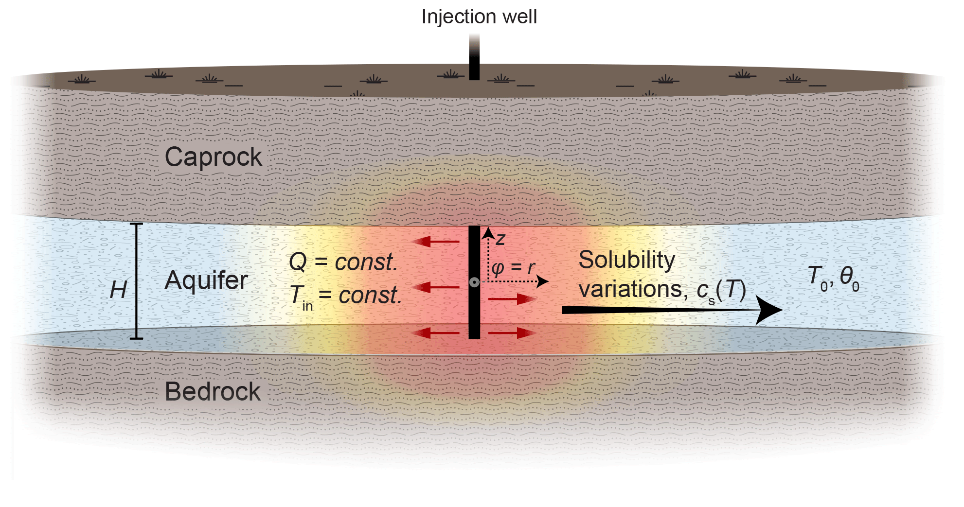
Figure 1Sketch of the reactive Lauwerier problem and the conceptual model for thermally driven reactive transport in geothermal systems (the radial case). Hot (or cold) fluid is injected into a confined aquifer between aquiclude bedrock and caprock at a constant flow rate, Q, and temperature, Tin. The initial temperature of the aquifer is T0, and its thickness is H. Downstream, along the flow path, heat is conducted from the aquifer through the confining layers. Thermal variations in the aquifer (color gradients) induce a change in solubility, cs(T), and hence disequilibrium and reaction, which in turn drive the evolution of the porosity of the aquifer from its initial value, θ0. z represents the vertical coordinate. In the main text, both polar and Cartesian geometries are considered, with φ=r or x, respectively. The origin of φ and z is defined at the center of the injection well. The injection well exhibits either axial (as shown in the sketch) or planar symmetry if Cartesian geometry is considered.
Downstream, along the flow path away from the injection point, heat is exchanged between the aquifer and the impermeable confining rock layers. Within the confining layers, heat is transported by conduction alone. The heat exchange and thermal variations in the aquifer induce changes in the solubility of the minerals (i.e., saturation concentration, cs(T)), which in turn trigger undersaturation and dissolution reactions or, conversely, supersaturation and precipitation reactions that modify the aquifer porosity, θ. Both removal or accumulation of minerals can occur depending on the injection temperature (colder or warmer than ambient) and the prograde or retrograde nature of the reactive minerals. Our radial setup pertains to injection from a single well or mimics natural localized thermal upwelling in fractured/faulted media of deep origin, discharging into the shallower aquifer (Craw, 2000; Micklethwaite and Cox, 2006; Roded et al., 2013, 2023; Tripp and Vearncombe, 2004). The planar source setup simulates injection wells arranged in a straight line (Lauwerier, 1955).
2.2 Main model assumptions
Here, the THC conceptual model shown in Fig. 1 is mathematically described using conservation equations for heat and reactive transport along with initial and boundary conditions. The thermal Lauwerier solution and the mathematical model involve several simplifying assumptions, the major ones of which are listed below. For a more comprehensive overview, expanded versions of the conservation equations are provided in Appendix A.
The underlying thermal assumptions include negligible basal (background) geothermal heat flow and an initial geothermal gradient compared to the heat input by the injected fluid. The aquifer is located at a significant depth, preventing heat transport to the surface; otherwise, greater heat exchange would occur between the aquifer and the caprock. This assumption regarding the depth also depends on the timescale of interest: the thermal front, which ascends with time, may not reach the surface on a short timescale. However, it may transport heat to the surface after a longer time (which can be estimated using tC).
Heat transport in the layers confining the aquifer is described by conduction and only in the vertical direction (z), neglecting lateral (φ) heat conduction. This assumption limits the applicability of the solution to scenarios involving large injected fluid fluxes. To assess the validity of this assumption, a thermal Péclet number, which compares heat advection in the aquifer to lateral heat conduction, , is used. PeT involves a length scale, l, at which substantial temperature variation occurs (e.g., larger than 2 % from the total temperature change, ΔT). An analysis using the parameter values in Table 1 and the results in Sect. 3 (i.e., a posteriori inspection) confirm that PeT≫1 at all times. Additionally, beyond the very early moments, the length scale of l should be larger than the vertical dimension of the aquifer, H, at which complete thermal mixing is assumed (l≫H). This assumption may not be applicable if a thick aquifer (i.e., large H) is considered and substantial vertical temperature gradients are expected to develop.
Furthermore, conduction and solute diffusion within the aquifer groundwater are neglected because the respective thermal (PeT) and solute (Pes) Péclet numbers are assumed to be large. Fluid and solid properties, such as density and heat conductivity, are considered constant and independent of temperature. It is noted that for CO2 applications, the assumption of constant density and incompressibility may not be appropriate for a CO2-rich phase (supercritical or gas) with moderate temperature changes (e.g., ΔT>40 °C).
Furthermore, the specific reactive surface area, As (L2 to L−3 of the porous medium), is considered constant here and assumed not to change as reaction progresses. In most instances, this assumption does not weaken the applicability of the solution since As may vary widely across different rock lithologies, e.g., from 10−1 m−1 in fractured media (Deng and Spycher, 2019; Pacheco and Van der Weijden, 2014) to above 105 m−1 for porous rocks (Mostaghimi et al., 2013; Noiriel et al., 2012; Seigneur et al., 2019) and can often only be estimated very roughly (e.g., within an order of magnitude accuracy). Furthermore, As can evolve with the reactive flow in a way that is difficult to estimate (Noiriel, 2015; Seigneur et al., 2019). If large porosity changes occur, the inherent assumption of a constant As can limit the applicability of the solutions.
2.3 The basic conservation equations
Neglecting heat conduction in the radial direction, r, the heat conduction equation in the rock confining the aquifer above and below is given by
where T represents temperature; t denotes time; z is the vertical coordinate, with its origin at the center of the injection well; and H is the aquifer thickness (see Fig. 1). The quantity is the thermal diffusivity [L2 T−1], where the subscript b indicates bulk rock, K is the thermal conductivity, and Cp is the volumetric heat capacity (Chen and Reddell, 1983; Stauffer et al., 2013).
Assuming that heat transport in the fluid along the aquifer is governed by advection and that complete mixing occurs in the aquifer transverse direction (z), a depth-averaged heat-transport equation can then be formulated for the aquifer region:
where subscript f denotes fluid and u(r) is the radial superficial velocity (or Darcy flux), which can be determined from the total volumetric flow rate, Q, using (assuming u to be uniform along the z direction of the aquifer; Andre and Rajaram, 2005; Lauwerier, 1955). Function Θ accounts for the heat exchange between the aquifer and the confining rock located above and below, calculated using Fourier's law, with continuous temperature assumed at the interfaces:
The factor of 2 accounts for the rock both above and below the horizon (Stauffer et al., 2013).
The solute transport advection–reaction equation in the aquifer is
Here, c is the solute concentration [M L−3] and Ω is the reaction term (Chaudhuri et al., 2013; Szymczak and Ladd, 2012). Equation (4) is derived by neglecting transient and diffusive terms in the advection–diffusion–reaction equation (Eq. A3). The justification for the quasi-static approximation used when deriving Eq. (4) lies in the separation of timescales between heat conduction (tC) in the confining rocks and mineral alteration (tM) and the relaxation of solute concentration (tA) (for in-depth analysis and discussion, see Appendix B and, e.g., Detwiler and Rajaram, 2007; Ladd and Szymczak, 2017; Lichtner, 1991; Roded et al., 2020; Sanford and Konikow, 1989).
Here, we assume a surface-controlled reaction and first-order kinetics:
where As is the specific reactive surface area and λ is the kinetic reaction rate coefficient [L T−1], here assumed to be constant (Dreybrodt et al., 2005; Seigneur et al., 2019). Λ is denoted as the solute disequilibrium and is defined as the difference between the concentration of dissolved ions and saturation (equilibrium) concentrations, cs,
Thus, the solute disequilibrium, Λ, is negative for undersaturation and positive for supersaturation. cs is calculated as follows:
Here, T0 represents the initial temperature in the aquifer and the parameter . Equation (7) assumes a linear relationship between cs and T, with a constant proportionality factor, β, which is positive for minerals of prograde solubility and negative for minerals of retrograde solubility (Al-Sulaimi, 2015; Corson and Pritchard, 2017; Woods, 2015).
Given the reaction rate (Eq. 5), the change in porosity, θ, can be calculated as follows:
where csol is the concentration of the soluble solid mineral and ν accounts for the stoichiometry of the reaction. In the case of planar flow and Cartesian coordinates, r can be replaced by x in the equations above, while Eq. (2) takes the following form:
where u here is the spatially uniform fluid velocity in the x direction.
2.4 Initial and boundary conditions
The initial conditions involve a uniform value of temperature T0 throughout the medium. The boundary conditions at the injection well (φ=0) include a constant rate of fluid injection at temperature Tin and initially zero solute disequilibrium, Λ=0 (Eq. 6). The caprock and bedrock thickness and aquifer extent are assumed to be infinite.
2.5 Solution of the reactive Lauwerier problem
2.5.1 Axisymmetric (radial) flow
Aquifer temperature
The solution of Eqs. (1) and (2) for the temperature distribution in the aquifer (known as the Lauwerier solution) for the radial case is given by
Here, erfc is the complementary error function, is the difference between injection and initial aquifer temperature, and ζ is defined as
The time variable, , and the solution given by Eq. (10) holds when (Stauffer et al., 2013). We additionally assume long enough time and conditions where (see Appendix C for analysis of the validity of this assumption). Furthermore, to simplify the equations, we assume equal heat capacities for both the confining rocks and the aquifer. To account for non-uniform heat capacities alternative form of Eq. (10) can be used (refer to Eqs. 3.122 and 3.131 and associated definitions in Stauffer et al., 2013).
Reactive solute transport
We begin by substituting Eq. (6) into Eq. (4) to obtain
The derivative can then be expressed by differentiating the relationship in Eq. (7),
and further substituting Lauwerier solution (Eq. 10), which provides
Next, substituting Eq. (14) into Eqs. (13) and (12) results in a linear inhomogeneous differential equation. Assuming saturation conditions at the inlet and the boundary condition of leads to the following solution:
where erf is the error function and . Appendix D presents an approximation for Eq. (15) which is useful for efficient computation and prevents integer overflow (Press et al., 2007).
Given the reaction rate (Eq. 5), the erosion and porosity change can be calculated using the solid erosion equation (Eq. 8). Substituting Eq. (15) into Eq. (8), integrating over time, and using the initial condition of results in a closed-form expression for the temporal and spatial evolution of porosity, θ:
2.5.2 Planar flow
In the Cartesian case, with injection along a line, the Lauwerier solution is
where ω is defined as
and . Similarly, to the radial case, the solution holds at sufficiently long times, for which .
Following the analogous steps as in the radial case, the solution is derived by
and
where .
In this section, we use the radial solutions presented in the previous section to examine two common scenarios: (I) injection of CO2-rich hot water into a carbonate aquifer and (II) injection of silica-rich hot water into a sandstone aquifer. These scenarios result in cooling-induced calcite dissolution and silica precipitation, respectively. The subsequent porosity evolution within these systems (Eqs. 16 and 20) is then used to estimate the evolution of aquifer permeability. These scenarios are pertinent, for instance, in aquifer thermal storage, reinjection of geothermal water at shallow depths, or applications of groundwater storage and recovery (Diaz et al., 2016; Fleuchaus et al., 2018; Maliva, 2019).
3.1 Aquifer properties and injection conditions
Here, we discuss conditions for thermally induced reactivity in carbonates and sandstone aquifers and the parameter values assigned in the simulations (Table 1). Regarding the description of the kinetics of these systems, calcite dissolution can often be complex, involving various chemical species and reactions of varying orders (Dreybrodt, 1988; Plummer et al., 1978). However, for a wide range of pH values, it can be simplified and described by assuming a linear dependence on undersaturation or acid concentration. Specifically, first-order kinetics are commonly employed to study natural karst formations (pH ∼ 6; Dreybrodt et al., 2005; Palmer, 1991), and dissolution under the acidic conditions common in engineering applications (pH ∼ 3; Hoefner and Fogler, 1988; Peng et al., 2015) or in geothermal systems of high CO2 partial pressure, PCO2 (pH∼ 5; Coudrain-Ribstein et al., 1998; Lu et al., 2020; Roded et al., 2023). Silica precipitation can be well described by first-order kinetics (Carroll et al., 1998; Ji et al., 2023; Pandey et al., 2015; Rimstidt and Barnes, 1980).
Table 1Parameter values used in the simulations.
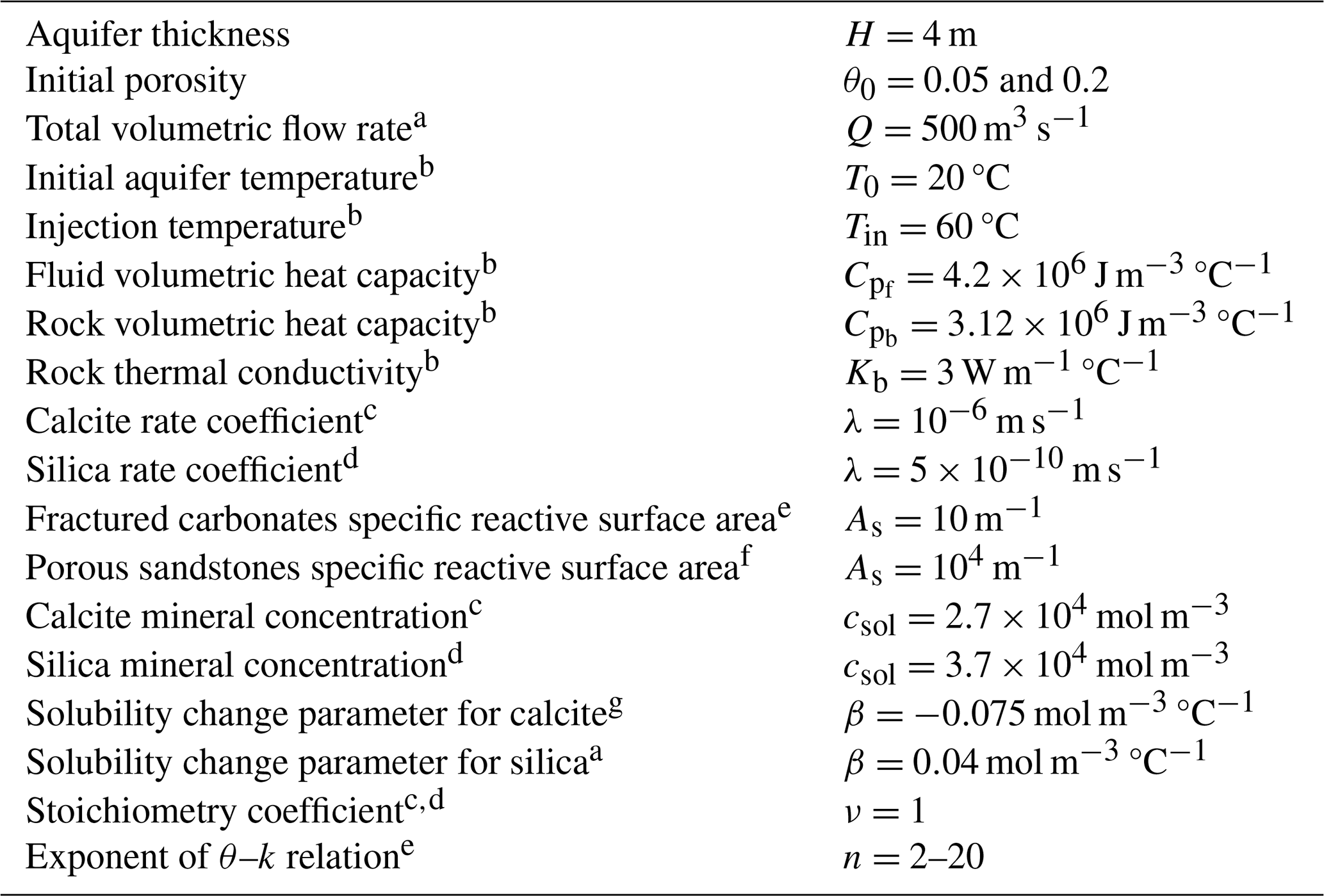
a Glassley (2014). b Huenges and Ledru (2011). c Palmer (1991). d Rimstidt and Barnes (1980). e See text. f Hussaini and Dvorkin (2021) and Lai et al. (2015). g Roded et al. (2023).
We also exploit approximately linear temperature–solubility dependence over the temperature range studied here (between T0=20 °C and Tin=60 °C) and assign a constant value to β (Eq. 7; Andre and Rajaram, 2005; Glassley, 2014; Rimstidt and Barnes, 1980; Roded et al., 2023). Additionally, it should be noted that in carbonates, the temperature–solubility relation strongly depends on PCO2: higher PCO2 values result in larger increases in cs as the water cools (i.e., the magnitude of β is larger; see Fig. 2b in Roded et al., 2023, and Andre and Rajaram, 2005; Palmer, 1991). Here, in accordance with typical conditions in geothermal systems, we consider injection of water with PCO2 = 0.03 MPa (Coudrain-Ribstein et al., 1998; Lu et al., 2020).
In the simulations, we assign characteristic porosity (θ) and reactive surface area (As) for the different aquifer types. In accordance with common field observations, we consider a carbonate aquifer in which flow and dissolution are focused in the permeable fracture network and a porous sandstone aquifer characterized by high intergranular permeability (Bear and Cheng, 2010; Jamtveit and Yardley, 1996). The different aquifer characteristics are reflected in significant differences in θ and As for the different aquifer types. Specifically, carbonates are often characterized by permeability contrasts spanning orders of magnitudes between the fractures and the rock matrix (Dreybrodt et al., 2005; Lucia, 2007). Consequently, transport in the matrix occurs mostly by slow diffusion, and the reaction within the matrix can be neglected. Hence, only the reactive surface area, As, of the fractures effectively participates in the reaction (Deng and Spycher, 2019; Maher et al., 2006; Pacheco and Alencoão, 2006; Seigneur et al., 2019). In this case, θ can be minimal (Lucia, 2007) and As is orders of magnitude smaller compared to its value in porous sandstones (Hussaini and Dvorkin, 2021; Lai et al., 2015; Pacheco and Alencoão, 2006; Pacheco and Van der Weijden, 2014; Seigneur et al., 2019). This disparity can lead to substantial differences in characteristic alteration rates and Damköhler numbers in these systems (Ladd and Szymczak, 2021; Lucia, 2007; Seigneur et al., 2019).
Specifically, in the case of fractured rocks as described above, we calculate the reactive surface area using , where κ is the fracture density (defined as the number of fractures per unit volume), the factor of 2 accounts for the presence of two surfaces, and RF is the roughness factor (Deng et al., 2018). Assuming m−3 and RF = 1.35 results in As=0.1 m−1. Typical values of κ and fracture spacing can span a substantial range and may be higher or lower (Narr and Suppe, 1991; Scholz, 2019). Here, it is further assumed that the fracture density is high and the network is of high connectivity, allowing it to be treated as a continuum (Anderson et al., 2015; Sahimi, 2011). We consider here an injection flow rate of Q=500 m3 d−1, which falls within the typical range of flow rates observed in relevant applications, such as geothermal systems (Glassley, 2014) or groundwater storage and recovery (Maliva, 2019). The injection temperature is set to Tin=60 °C, and aquifer ambient temperature is set to T0=20 °C (ΔT=40 °C). To obtain the results, in this section, the solutions were implemented in MATLAB code (MATLAB, 2022). Appendix D details the use of the approximated Eq. (D2) in calculating the results in Figs. 2 and 3.
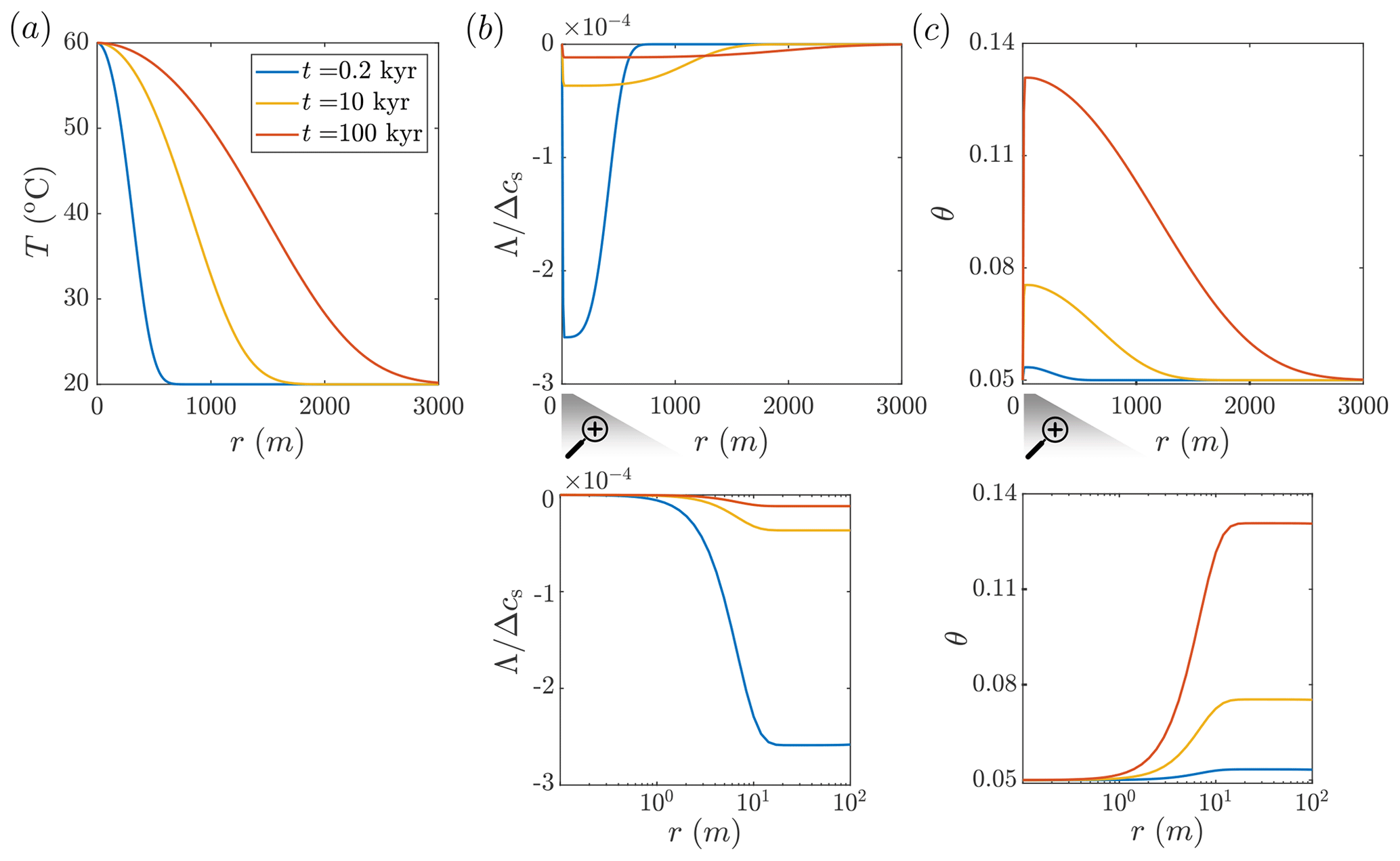
Figure 2Carbonate aquifer dissolution by cooling hot water. Temperature, T; solute disequilibrium, Λ; and porosity, θ, in the aquifer are plotted as functions of the radial position, r, at different times (computed using Eqs. 10, 16, and D2). (a) The hot flow cools gradually as it travels through the aquifer, transferring heat to the confining rocks, thereby causing them to warm over time and the thermal front to progress downstream. (b) Cooling induces undersaturation (negative disequilibrium, Λ; see Eq. 6), which is of a relatively small magnitude due to the rapid kinetics of calcite dissolution. Λ is normalized by the total solubility change in the system, Δcs (refer to the text for the definition of Δcs). The water is hot and saturated at the inlet, c=cs(Tin). Undersaturation quickly develops near the inlet (r≈20 m, as shown in the magnification) and then gradually diminishes due to dissolution reactions further along the flow path (Λ approaches zero). As the thermal front propagates over time, and thermal gradients diminish, the Λ curves also flatten. (c) Corresponding to Λ variations, a porosity profile develops over time (see the magnification for the inlet-adjacent region).
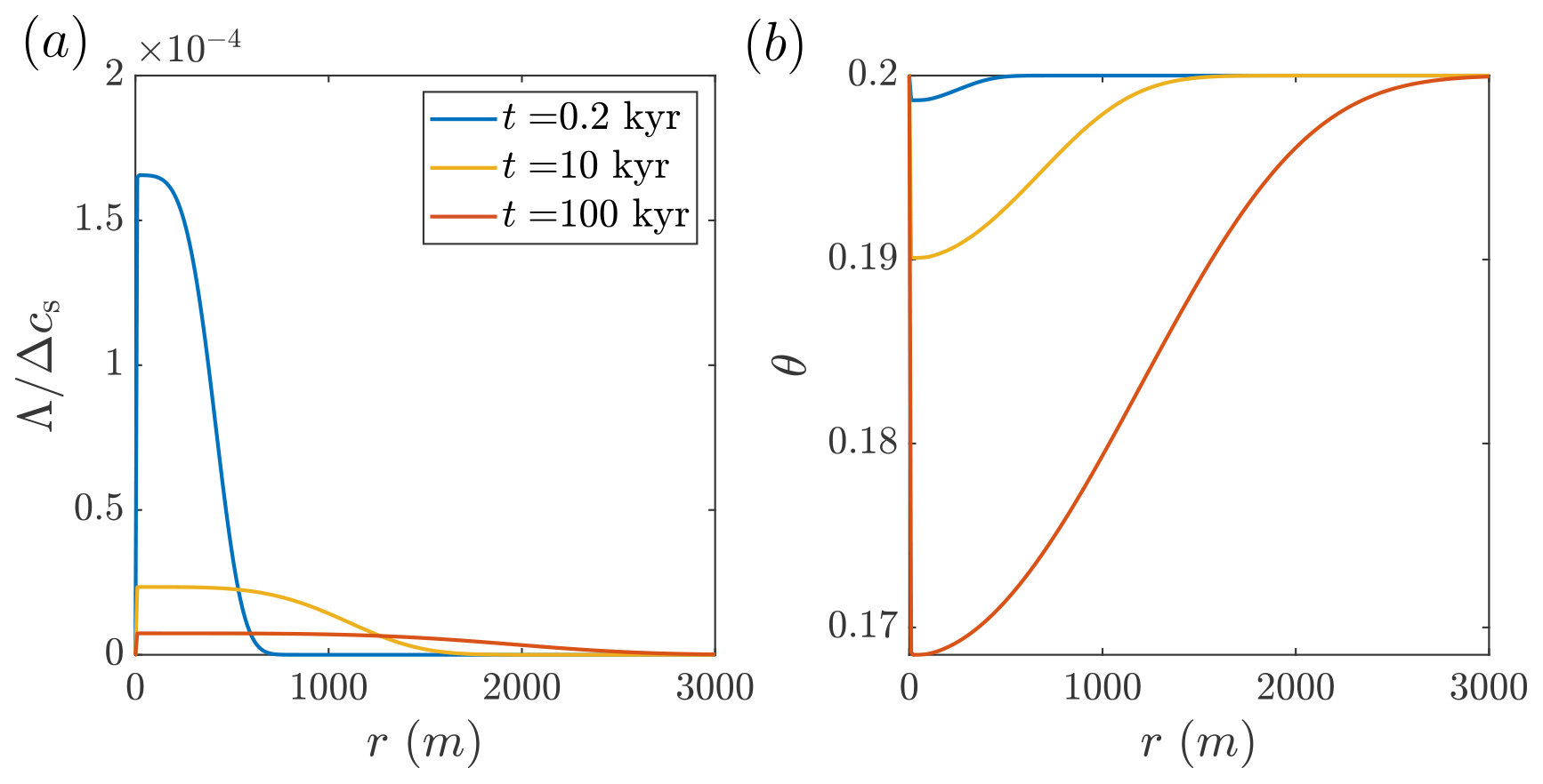
Figure 3Silica precipitation in a sandstone aquifer by cooling hot water. The calculated solute disequilibrium, Λ, and porosity, θ, as functions of the lateral position, r, are shown at different times since the beginning of the injection (calculated using Eqs. 16 and D2; the temperature profile is given in Fig. 2a). The reactive transport processes in this case are similar to the carbonate dissolution system shown in Fig. 2, with insets Fig. 2b and c being approximately mirror images of panels (a) and (b), showing supersaturation and porosity reduction. (a) As a result of cooling, solute disequilibrium corresponding to supersaturation (Λ; Eq. 6) develops, which is of a small magnitude due to the high reaction rates (Λ is scaled by the total solubility change in the system, Δcs; refer to the text for the definition of Δcs). The water enters hot and saturated at the inlet, c=cs(Tin), and, subsequently, Λ increases rapidly and then gradually diminishes downstream due to the reaction. The advancement of the thermal front over time and lower gradients lead to the flattening of Λ curves. (b) In accordance with Λ, an extensive porosity profile develops over time.
3.2 Carbonate aquifer dissolution by cooling water
In Fig. 2, the results of CO2-rich hot water injection into a carbonate aquifer at successive times since the beginning of the injection are shown (Eqs. 10, 16, and D2 are solved for t=0.2, 10, and 100 kyr). During the radial flow within the aquifer, the hot fluid cools by transferring heat into the confining layers, which heat up with time, resulting in the gradual advancement of the thermal front downstream (Fig. 2a). The cooling induces solute disequilibrium (Λ) associated with undersaturation (note that Λ is negative for undersaturation and positive for supersaturation; see Eq. 6). The magnitude of Λ in the aquifer is small compared to the absolute solubility change in the system, , i.e., between cs(Tin) at the injection point and cs(T0) at ambient conditions ( %; see Fig. 2b). The small magnitude of disequilibrium is associated with relatively high PCO2 considered here (0.03 MPa) and rapid kinetics under these conditions. The quasi-equilibrium conditions may allow for the simplification and calculation of the local reaction rate from transport processes alone, regardless of kinetics, referred to as the so-called “equilibrium model” (Andre and Rajaram, 2005; Bekri et al., 1995; Golfier et al., 2002; Lichtner, 1991), which will be the subject of a future research.
Although the magnitude of disequilibrium, Λ, is small, it controls the alteration of the aquifer and the evolution of its properties. Significantly, because the water at the inlet is hot and saturated with calcite, c=cs(Tin), disequilibrium, and reaction rate are zero at the inlet, leading to no change in the porosity there (see Figs. 2b and 3c and their magnifications). Disequilibrium (undersaturation) sharply develops downstream of the injection site, first forming a small minimum (at r≈20 m) and gradually increasing to zero at greater distances. Undersaturation and dissolution along the flow path are controlled by the interplay of three processes: (I) dissolution reducing undersaturation (i.e., Λ becomes closer to zero), (II) progressive cooling increasing undersaturation, and (III) advection–transport–reaction products (i.e., calcium ions) radially outward from the well, helping maintain undersaturation. Here, the effect of fluid velocity and advection decays with a distance of .
High advection and cooling rates near the inlet result in the abrupt formation of undersaturation (i.e., negative Λ). Further downstream, undersaturation diminishes due to dissolution reactions. As the thermal front advances downstream over time and the temperature gradients diminish along the aquifer, the Λ curve flattens and becomes more elongated (see curves for t=10 and 100 kyr in Fig. 2b). Due to the disequilibrium, porosity grows with time. The porosity sharply increases near the inlet and then gradually decreases downstream (Fig. 2c). The porosity changes are extensive and take place over an aquifer area of ∼30 km2 within a relatively short geological timescale of 100 kyr, resulting in the addition of significant void space of thousands of cubic meters ( m3).
An essential assumption underlying the solutions in Sect. 2 and the results depicted in Fig. 2 is the assumption of spatial uniformity and symmetry of reactive flow. In practical scenarios, however, dissolution instabilities can emerge at the reaction front. These instabilities, owing to the positive feedback between reaction and transport, may evolve into dissolution channels, often referred to as wormholes (Aharonov et al., 1997; Budek and Szymczak, 2012; Chadam et al., 1986; Ortoleva et al., 1987; Roded et al., 2018, 2021). The wormholes concentrate reactive flow, resulting in heterogeneous flow fields that cannot be accurately represented by assuming symmetry and uniformity. In such a case, the results of Fig. 2 can only be regarded as an average solution, which is not accurate locally.
Isothermal dissolution, driven by undersaturation of the incoming solution is known to be unstable in the radial geometry for a large-enough solute Péclet number, Pes, and intermediate Damköhler numbers. The Damköhler number here is given by and represents the ratio between advective and reactive timescales (Daccord, 1987; Grodzki and Szymczak, 2019; Kalia and Balakotaiah, 2007; Xu et al., 2020). However, in our case, the cooling of the solution renews its aggressiveness, hence extending the penetration length in the system which may influence the stability of the reactive front (Xu et al., 2020). The effect of renewed aggressiveness by considering solubility gradients was studied for planar reactive flow in Aharonov et al. (1997) and Spiegelman et al. (2001) but requires further investigation for radial flow and taking into account coupling with heat transfer.
3.3 Silica precipitation by cooling water
Here, we consider the injection of hot silica-rich water that cools, becoming supersaturated and leading to silica precipitation, consequently reducing void space and permeability. While the previous case involved dissolution, this one involves precipitation; however, the thermal and reactive transport processes are similar in both cases (with approximately mirror-image Λ and θ profiles; see Figs. 2b, c and 3a, b).
Similarly to the previous section, the low magnitude of Λ suggests that the reaction rate (Eq. 5) is relatively high compared to transport processes, effectively reducing disequilibrium, Λ. It is noted that the reaction rates are high in both systems despite the orders-of-magnitude differences in the kinetic rate coefficient ( m s−1 for calcite dissolution compared to m s−1 for silica precipitation). However, this difference is largely compensated by the contrast between the reactive surface area of the porous sandstone and fractured carbonate aquifers (As=104 m−1 compared to 10 m−1, respectively). It should also be noted that while precipitation of crystalline and non-crystalline (amorphous) silica is characterized by relatively high rates, dissolution of quartz and silica polymorphs is typically slower by several orders of magnitude (Rimstidt and Barnes, 1980).
While the reaction rates are high in both systems, differences exist in the absolute magnitude of porosity change resulting from the injection. For example, the maximal porosity change in the aquifer due to silica precipitation is approximately Δθmax≈0.03, whereas for the carbonate case it is around Δθmax≈0.08 (where and θmax denote the maximal porosity change along the profile). The predicted lower porosity change in silica arises mostly due to its lower total solubility change, Δcs, and the reduced dependence of mineral solubility on temperature, expressed here by the β parameter (see Table 1). This conclusion is further supported by the fact that no disequilibriated fluid exits the system: the fluid flows out from the system at r=3000 m at a temperature that is close to the ambient temperature, T0 (Fig. 2a), and chemically equilibrated (Λ=0; Figs. 2b and 3a).
3.4 Permeability evolution of the aquifers
The porosity changes affect the aquifer hydraulics. Here, we calculate the effective aquifer permeability, keff, within a distance, R, around the well. keff is calculated based on the relationship between the local porosity and permeability, utilizing the power-law relation , where k0 and θ0 are the initial permeability and porosity (the steps for the calculation of keff are presented in Appendix E). The exponent n depends on various factors, such as medium microstructural details and the nature of the alteration processes (Seigneur et al., 2019; Steefel et al., 2015; Vafaie et al., 2023). The limited predictive capabilities of k–θ relations, including instances where counter trends of porosity and permeability changes occur (Garing et al., 2015), have been previously noted (e.g., Sabo and Beckingham, 2021). Here, it is applied to evaluate general trends, which, with the exception of unique cases, remain valid regardless of the porosity–permeability relation used.
The wide range of heterogeneous microstructures in rocks and sediments and their response to different reactive-flow regimes lead to a large variability in the exponent n values. For example, for relatively uniform spatial dissolution, n can range from ∼3 to a few dozen for the early stages of flow or when wormholes develop (Hao et al., 2013; Roded et al., 2020; Vafaie et al., 2023). For precipitation, n typically ranges from ∼2 up to above 10 (Aharonov et al., 1998; Hommel et al., 2018; Seigneur et al., 2019).
Figure 4 shows keff evolution over time for representative exponent values within a distance of R=3 km. The rapid increase in carbonate aquifer permeability indicates (in agreement with previous works, Agar and Geiger, 2015; Andre and Rajaram, 2005; Dreybrodt et al., 2005) that keff can be substantially altered within relatively short geological timescales. Specifically, the results suggest that keff can even increase by several tens of percents within tens to hundreds of years. Conversely, significant keff alterations due to silica precipitations (10 %–50 % reduction) involve typical timescales of tens of thousands of years. These findings are consistent with previous observations of dissolution and precipitation driven by a solubility gradient (e.g., Aharonov et al., 1997), emphasizing differences between these processes, as embodied in the exponent n. Moreover, under constant pressure (instead of constant flux) boundary conditions, this effect will be enhanced due to a positive (negative) feedback during dissolution (precipitation) (Aharonov et al., 1997).
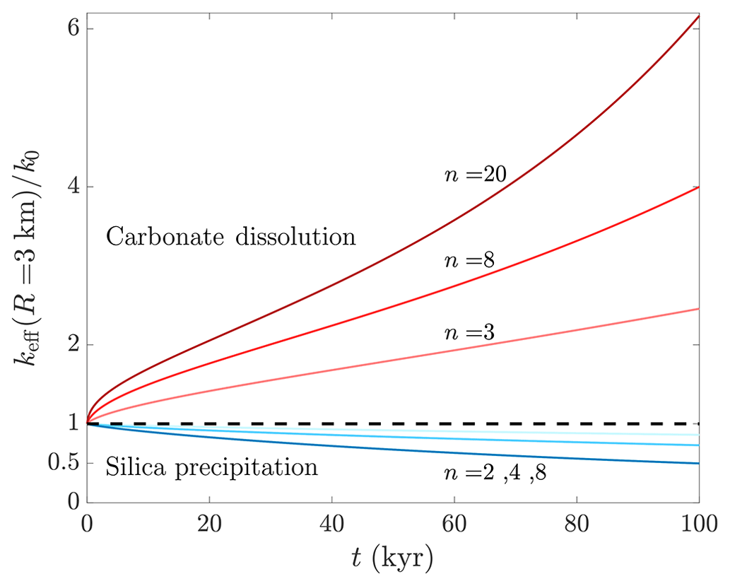
Figure 4Evolution of aquifer effective permeability due to dissolution and precipitation. The effective permeability is keff, and t is time; red and blue curves designate carbonate dissolution and silica precipitation, respectively. keff is calculated within a radius of R=3 km from the well and is normalized by its initial value, k0. The power-law θ–k relation is used to determine keff from the local porosity, θ(r), and permeability, k(r), with typical exponent values of n=3–20 for dissolution and n=2–8 for precipitation. keff can be substantially altered in carbonate aquifers due to dissolution even within tens to hundreds of years, while tens of thousands of years are required for similar magnitudes of change caused by silica precipitation.
In this paper, we considered non-isothermal injection into a confined aquifer and the settings and solution of the so-called Lauwerier problem to derive coupled thermally driven reactive transport solutions (reactive Lauwerier problem). The presented solution is among the very limited number of analytical solutions available in the field of thermo-hydro-chemical (THC) flows in porous media. The THC scenarios considered here involved geochemical disequilibrium and reactions induced by thermally driven solubility changes, leading to mineral dissolution or precipitation. In the first section, solutions were derived for the evolution of solute concentration in radial and planar cases. These derivations utilized the non-isothermal Lauwerier solution to calculate the temperature-dependent solubility, which was then substituted into the reactive transport equation. Subsequently, the obtained concentration closed-form solutions were used to derive expressions for the porosity change in the aquifer.
In the second section, these solutions were employed to study two common cases in geothermal and water resource systems, exhibiting opposite feedback on porosity evolution: (I) injection of hot CO2-rich water into a fractured carbonate aquifer, leading to cooling and dissolution, and (II) injection of hot silica-rich water into a sandstone aquifer, leading to silica precipitation. The resulting porosity profiles were then used to calculate the hydraulic changes and effective aquifer permeabilities. The results show that the timescale of porosity development in these systems is on the order of thousands to tens of thousands of years depending on the THC conditions (in agreement with previous works, Andre and Rajaram, 2005; Roded et al., 2023). Despite the often faster kinetics of carbonate dissolution compared to silica precipitation, similar timescales are observed in both systems. This is attributed to the high specific reactive surface area of sandstones, which enhances the reaction rate, compensating for the differences in kinetics between carbonate dissolution and silica precipitation. However, substantial hydraulic changes occur much faster in dissolving carbonate aquifers, possibly within tens to hundreds of years, primarily due to the rapid enhancement of permeability resulting from dissolution and a flow-enhanced feedback.
It is worth noting that under the typical conditions considered, the reaction rates are high and the geochemical disequilibrium in these systems is minimal (i.e., quasi-equilibrium). In such conditions, the equilibrium assumption, which simplifies calculations in the reactive Lauwerier problem and comprises an ongoing area of inquiry, may be applied. The solutions and analyses provided contribute to the understanding of natural and engineered hydrothermal systems, such as aquifer storage and recovery (ASR) and thermal energy storage (ATES) applications. Additionally, these solutions can aid in the development and benchmarking of coupled numerical models.
A1 Aquifer temperature
Assuming radial symmetry and that heat transport through the rocks confining the aquifer is governed by conduction, the heat equation in polar coordinates becomes
where T is the temperature; t is time; r and z are the radial and vertical coordinates, respectively, with their origin at the injection well center; and H is aquifer thickness (see Fig. 1). The quantity is the thermal diffusivity, where the subscript b denotes bulk rock, K is the thermal conductivity, and Cp is the volumetric heat capacity (Stauffer et al., 2013).
Assuming that heat transport in the fluid within the aquifer is governed by advection and conduction, the heat-transport equation can then be expressed as
where subscript f denotes fluid and u(r) is the radial superficial velocity (or Darcy flux) and can be calculated from the total volumetric flow rate, Q, using (assuming uniformity of u along the z direction of the aquifer; Andre and Rajaram, 2005; Chaudhuri et al., 2013).
Assuming complete thermal mixing in the transverse direction (z) of the aquifer allows us to establish the depth-averaged Eq. (2) in the main text. In this case, the heat exchange between the aquifer and the confining rocks is integrated within the heat exchange term (Θ).
A2 Reactive transport
Similarly, the solute transport advection–diffusion–reaction equation in the aquifer is
where c is the solute concentration [M L−3], D is the molecular diffusion coefficient, and Ω is the reaction term (Chaudhuri et al., 2013; Szymczak and Ladd, 2012). The equations describing the reaction term, Ω; saturation concentration, cs; dependence on the temperature; and porosity change are given in Sect. 2.3 in the main text (Eqs. 5, 7, and 8, respectively).
In the case of planar flow and Cartesian coordinates, Eqs. (A1)–(A3) above take the following form:
and
Here u is the constant velocity in the x direction.
In our reactive transport calculations and Eq. (4) used for developing the solutions in Sect. 2, we adopt the quasi-static approach (Detwiler and Rajaram, 2007; Ladd and Szymczak, 2017; Lichtner, 1991; Roded et al., 2020; Sanford and Konikow, 1989) and neglect the transient term (present in Eqs. A3 and A6). However, it is noted that temporal variations may take place due to changes in the temperature field and their effect on the solubility, as arises from Eq. (7).
The justification for the quasi-static assumption lies in the significant separation of characteristic timescales in the system. There are three important timescales in our problem: (I) the timescale governing reactant transport (tA), (II) the timescale of mineral chemical alteration (tM), and (III) the characteristic timescale of conductive heat transport (tC). The latter affects the solubility of aquifer minerals, thus influencing reaction and solute transport. Specifically, the conditions for the validity of quasi-static assumption are that tC and tM are several orders of magnitude larger compared to reactant transport relaxation time, tA (i.e., tA≪tM and tA≪tC).
For example, in relatively fast-reacting natural carbonate systems, the doubling of initial pore size or fracture aperture due to dissolution typically occurs over a timescale of months to years. In silicate minerals, these timescales are of the order of thousands of years (Dove and Crerar, 1990; Ladd and Szymczak, 2021; Szymczak and Ladd, 2012; Zhu, 2005). Similarly, the characteristic timescale for the conduction processes in the confining rocks (tC) is commonly several orders of magnitude longer than the relaxation time for reactant transport (tA), which essentially maintains a steady state throughout the aquifer evolution. These timescales are given by
where lA and lC are characteristic length scales of advection and heat conduction, respectively, uA denotes the characteristic Darcy flux [L T−1], αb is the bulk thermal diffusivity, θ0 represents the initial porosity, As stands for the specific surface area of the reacting mineral [L2 L−3], and λ is the kinetic reaction rate coefficient [L T−1]. Here, , where csol is the mineral concentration in the solid, ν accounts for the stoichiometry of the reaction, and Δcs is the variation in solubility induced by thermal changes along the flow path. Δcs is calculated here using the difference between the injected saturated fluid concentration, , and the downstream saturation at the background aquifer temperature, c=cs(T0) (i.e., ). γ is often referred to as the acid capacity number, representing the ratio between (I) under(super)-saturation created when cooling or heating the solution from Tin to T0 and (II) the number of molecules in a unit volume of a mineral, csol (see parameter values in Table 1; Ladd and Szymczak, 2017; Roded et al., 2020).
In the calculation of timescale tA, the characteristic length scale, lA, can be set to be equal to the reactive front length, which in turn is affected by the thermal front length along the aquifer (φ direction). The length scale, lC (used in tC calculation) corresponds to the thermal front that develops in the confining insulating layers in the z direction, which elongates over time. In practice, the timescale separation between tA and tM and tC can also be validated a posteriori. Under a large set of conditions, the reaction rate is limited solely by advective transport (i.e., regardless of kinetics), which leads to small geochemical disequilibrium (Andre and Rajaram, 2005). In such conditions, the actual timescale of matrix deformation will be much longer than predicted by the expression given above for tM.
In this Appendix, the solution of Eq. (10) is compared to its approximated solution, when is assumed (Fig. C1). The results demonstrate that for times longer than 100 years, the differences between the solutions diminish, with a maximal error of 1.5 %, where the error is defined as , with TExt and TApr being the exact and approximated solutions. These results confirm the validity of the assumption of and the derived solutions for times longer than 100 years under the conditions considered.
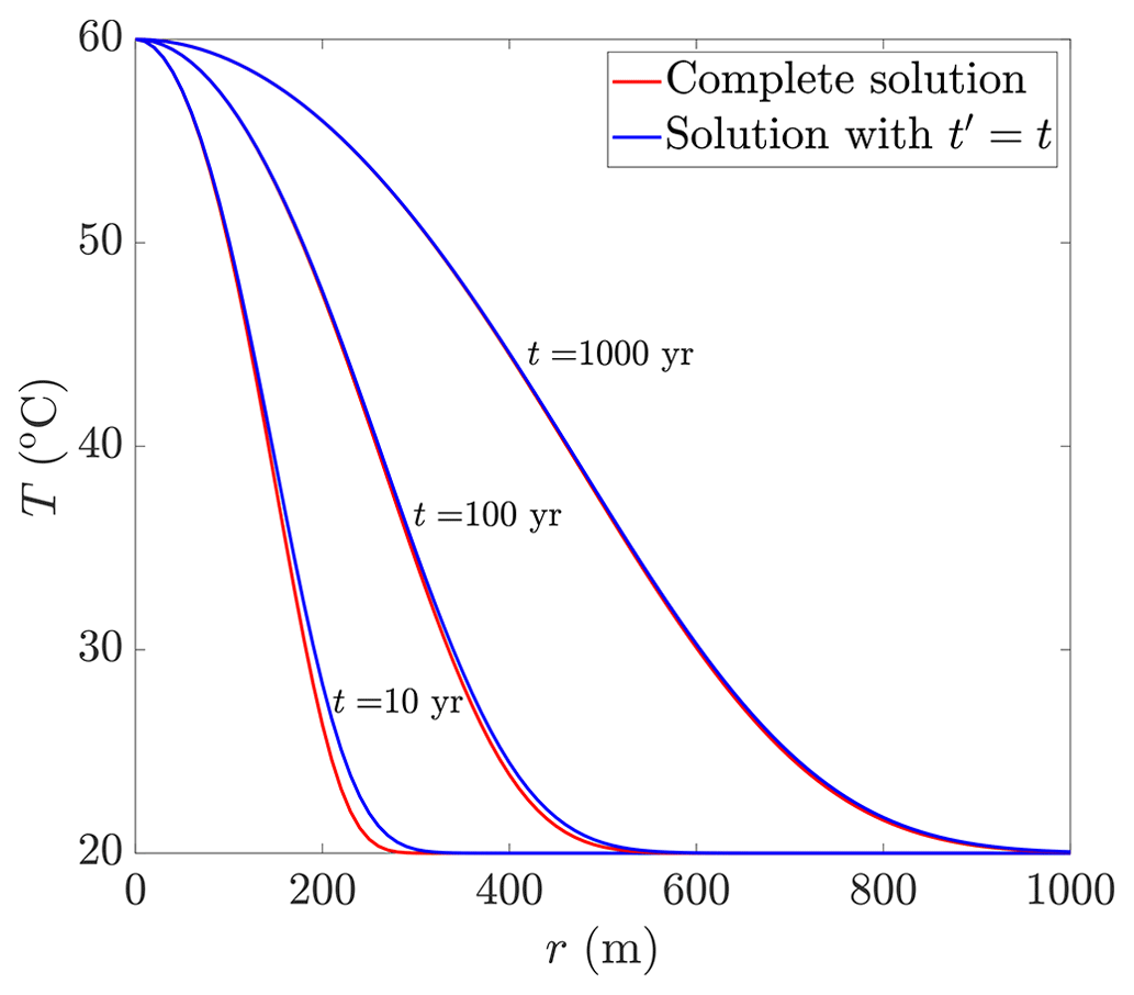
Figure C1Comparison of the full and approximate solution for the temperature profile. The approximate solution considers (Eq. 10). The results demonstrate that for times longer than 100 years, the differences between the solutions diminish, with a maximal error of 1.5 % (see text).
To obtain a solution by computational means and prevent an integer overflow (Press et al., 2007), it is useful to derive an approximate solution for Eq. (15) using the first-order asymptotic expansion of erf. Substituting this expansion into Eq. (15) leads to
and after further rearrangement, we finally arrive at
For the planar injection case, we obtain the following from Eq. (19):
To avoid integer overflow errors, Eq. (D2) is used to obtain the undersaturation profiles in Figs. 2b and 3a and is numerically iterated to solve for the porosity profile at later times (t≈100 kyr). The accuracy of the approximation of Eq. (D2) was verified by comparing it to the full solution in Eq. (15), which can be solved for early times (t≈1 yr). Furthermore, the accuracy of Eq. (D2) and the iterative solutions was further confirmed by solving for the porosity profile and comparing these results to those obtained using the full solution in Eq. (16) for t=10 kyr.
Using Darcy's law, we calculate an effective permeability, keff, for the aquifer around the well within a radius of r=R. The Darcy's law under these conditions is
where p and μ are the fluid pressure and viscosity and k the permeability. Integrating Eq. (E1) between r=0 and r=R leads to
and the effective permeability is
which is calculated by numerical integration over the porosity profile and the power law given in Sect. 3.4.
| Roman | T | Temperature [°C] | |
| As | Specific reactive surface area [m2 m−3] | u | Fluid velocity [m s−1] |
| c | Solute concentration [mol m−3] | uA | Characteristic velocity [m s−1] |
| cs | Saturation concentration [mol m−3] | x | Coordinate [m] |
| csol | Concentration of soluble solid [mol m−3] | y | Coordinate [m] |
| Cp | Volumetric heat capacity [J m−3 °C−1] | z | Coordinate [m] |
| D | Diffusion coefficient [m2 s−1] | Greek | |
| Da | Damköhler number | α | Thermal diffusivity [m2 s−1] |
| erf | Error function | β | Solubility change parameter [mol m−3 °C−1] |
| erfc | Complementary error function | γ | Acid capacity number |
| err | Error | Δ | Total difference |
| H | Aquifer thickness [m] | η | Parameter group [m−2] |
| k | Permeability [m2] | θ | Porosity |
| keff | Effective permeability [m2] | Θ | Heat exchange term [W m−2] |
| K | Thermal conductivity [W m−1 °C−1] | κ | Fracture density |
| l | Characteristic length scale [m] | λ | Reaction rate coefficient [m s−1] |
| lA | Characteristic length scale of advection [m] | Λ | Solute disequilibrium [mol m−3] |
| lC | Characteristic length scale of conduction [m] | μ | Fluid viscosity [Pa s] |
| lD | Characteristic length scale of diffusion [m] | ν | Stoichiometric coefficient |
| n | Exponent of θ–k relation | ζ | Parameter group [m−2] |
| p | Fluid pressure [Pa] | ρ | Density [kg m−3] |
| Pes | Solute Péclet number | σ | Parameter group [m−1] |
| PeT | Thermal Péclet number | φ | Lateral coordinate φ=r or x [m] |
| Q | Total volumetric flow rate [m3 s−1] | ω | Parameter group [m−1] |
| r | Coordinate [m] | Ω | Reaction rate [mol m−3 s−1]) |
| R | Effective permeability radius [m] | Subscripts | |
| RF | Roughness factor | Apr | Approximated value |
| t | Time [s] | b | Bulk rock |
| tA | Characteristic timescale of advection [s] | Ext | Exact value |
| tC | Characteristic timescale of conduction [s] | f | Fluid |
| tD | Characteristic timescale of diffusion [s] | in | Inlet |
| tM | Characteristic timescale of mineral alteration [s] | max | Maximum |
| t′ | Time parameter [s] | 0 | Initial average quantity |
The MATLAB codes and data produced in this study are available at https://doi.org/10.5281/zenodo.12531720 (Roded, 2024).
EA, RR, and PS: theoretical analysis. RR, EA, and PS: conceptualization. RR: numerical analysis and writing (original draft). RR, BL, and LED: geochemical modeling. RR, EA, LED, PS, MV, and BL: writing (review and editing).
The contact author has declared that none of the authors has any competing interests.
Publisher's note: Copernicus Publications remains neutral with regard to jurisdictional claims made in the text, published maps, institutional affiliations, or any other geographical representation in this paper. While Copernicus Publications makes every effort to include appropriate place names, the final responsibility lies with the authors.
This research has been supported by the Israel Science Foundation (ISF; grant no. 910/17 awarded to Einat Aharonov) and the National Science Centre (NCN, Poland) under CEUS-UNISONO grant no. 2020/02/Y/ST3/00121 awarded to Piotr Szymczak. The author thanks Atefeh Vafaie and an additional anonymous referee for their constructive comments.
This research has been supported by the Israel Science Foundation (grant no. 910/17) and the Polish National Science Centre (CEUS-UNISONO grant no. 2020/02/Y/ST3/00121).
This paper was edited by Alberto Guadagnini and reviewed by Atefeh Vafaie and one anonymous referee.
Abbasi, M., Khazali, N., and Sharifi, M.: Analytical model for convection-conduction heat transfer during water injection in fractured geothermal reservoirs with variable rock matrix block size, Geothermics, 69, 1–14, 2017.
Agar, S. M. and Geiger, S.: Fundamental controls on fluid flow in carbonates: current workflows to emerging technologies, Geol. Soc. Lond. Spec. Publ., 406, 1–59, 2015.
Aharonov, E., Whitehead, J. A., Kelemen, P. B., and Spiegelman, M.: Channeling instability of upwelling melt in the mantle, J. Geophys. Res.-Solid, 100, 20433, https://doi.org/10.1029/95JB01307, 1995.
Aharonov, E., Spiegelman, M., and Kelemen, P.: Three-dimensional flow and reaction in porous media: Implications for the Earth's mantle and sedimentary basins, J. Geophys. Res.-Solid, 102, 14821–14833, 1997.
Aharonov, E., Tenthorey, E., and Scholz, C. H.: Precipitation sealing and diagenesis: 2. Theoretical analysis, J. Geophys. Res.-Solid, 103, 969–981, 1998.
Al-Sulaimi, B.: The energy stability of Darcy thermosolutal convection with reaction, Int. J. Heat Mass Transf., 86, 369–376, 2015.
Anderson, M. P., Woessner, W. W., and Hunt, R. J.: Applied groundwater modeling: simulation of flow and advective transport, Academic Press, ISBN 978-0-12-058103-0, 2015.
Andre, B. J. and Rajaram, H.: Dissolution of limestone fractures by cooling waters: Early development of hypogene karst systems, Water Resour. Res., 41, W01015, https://doi.org/10.1029/2004WR003331, 2005.
Bear, J. and Cheng, A. H.-D.: Modeling groundwater flow and contaminant transport, Springer Science & Business Media, https://doi.org/10.1007/978-1-4020-6682-5, 2010.
Bekri, S., Thovert, J. F., and Adler, P. M.: Dissolution of porous media, Chem. Eng. Sci., 50, 2765–2791, 1995.
Bhat, S. and Kovscek, A.: Permeability modification of diatomite during hot fluid injection, in: SPE Western Regional Meeting, Bakersfield, California, May 1998, https://doi.org/10.2118/46210-MS, 1998.
Bonte, M., Stuyfzand, P. J., and Breukelen, B. M. van: Reactive transport modeling of thermal column experiments to investigate the impacts of aquifer thermal energy storage on groundwater quality, Environ. Sci. Technol., 48, 12099–12107, 2014.
Budek, A. and Szymczak, P.: Network models of dissolution of porous media, Phys. Rev. E, 86, 056318, https://doi.org/10.1103/PhysRevE.86.056318, 2012.
Carroll, S., Mroczek, E., Alai, M., and Ebert, M.: Amorphous silica precipitation (60 to 120 °C): Comparison of laboratory and field rates, Geochim. Cosmochim. Ac., 62, 1379–1396, 1998.
Chadam, J., Hoff, D., Merino, E., Ortoleva, P., and Sen, A.: Reactive infiltration instabilities, IMA J. Appl. Math., 36, 207–221, 1986.
Chaudhuri, A., Rajaram, H., and Viswanathan, H.: Early-stage hypogene karstification in a mountain hydrologic system: A coupled thermohydrochemical model incorporating buoyant convection, Water Resour. Res., 49, 5880–5899, 2013.
Chen, C. and Reddell, D. L.: Temperature distribution around a well during thermal injection and a graphical technique for evaluating aquifer thermal properties, Water Resour. Res., 19, 351–363, 1983.
Corson, L. T. and Pritchard, D.: Thermosolutal convection in an evolving soluble porous medium, J. Fluid Mech., 832, 666–696, 2017.
Coudrain-Ribstein, A., Gouze, P., and de Marsily, G.: Temperature-carbon dioxide partial pressure trends in confined aquifers, Chem. Geol., 145, 73–89, 1998.
Craw, D.: Fluid flow at fault intersections in an active oblique collision zone, Southern Alps, New Zealand, J. Geochem. Explor., 69, 523–526, 2000.
Daccord, G.: Chemical Dissolution of a Porous Medium by a Reactive Fluid, Phys. Rev. Lett., 58, 479–482, 1987.
Dávila, G., Dalton, L., Crandall, D. M., Garing, C., Werth, C. J., and Druhan, J. L.: Reactive alteration of a Mt. Simon Sandstone due to CO2-rich brine displacement, Geochim. Cosmochim. Ac., 271, 227–247, https://doi.org/10.1016/j.gca.2019.12.015, 2020.
Deng, H. and Spycher, N.: Modeling reactive transport processes in fractures, Rev. Mineral. Geochem., 85, 49–74, 2019.
Deng, H., Molins, S., Trebotich, D., Steefel, C., and DePaolo, D.: Pore-scale numerical investigation of the impacts of surface roughness: Upscaling of reaction rates in rough fractures, Geochim. Cosmochim. Ac., 239, 374–389, 2018.
Detwiler, R. L. and Rajaram, H.: Predicting dissolution patterns in variable aperture fractures: Evaluation of an enhanced depth-averaged computational model, Water Resour. Res., 43, W04403, https://doi.org/10.1029/2006WR005147, 2007.
Diaz, A. R., Kaya, E., and Zarrouk, S. J.: Reinjection in geothermal fields- A worldwide review update, Renew. Sustain. Energ. Rev., 53, 105–162, 2016.
Diersch, H.-J. and Kolditz, O.: Variable-density flow and transport in porous media: approaches and challenges, Adv. Water Resour., 25, 899–944, 2002.
Dove, P. M. and Crerar, D. A.: Kinetics of quartz dissolution in electrolyte solutions using a hydrothermal mixed flow reactor, Geochim. Cosmochim. Ac., 54, 955–969, 1990.
Dreybrodt, W.: Processes in karst systems: physics, chemistry, and geology, Springer Verlag, Berlin, New York, xii, 288 pp., https://doi.org/10.1007/978-3-642-83352-6, 1988.
Dreybrodt, W., Gabrovšek, F., and Romanov, D.: Processes of speleogenesis: A modeling approach, Carsologica, edited by: Gabrovšek, F., Založba ZRC, Ljubljana, 375 pp., ISBN 961-6500-91-0, 2005.
Fleuchaus, P., Godschalk, B., Stober, I., and Blum, P.: Worldwide application of aquifer thermal energy storage – A review, Renew. Sustain. Energ. Rev., 94, 861–876, 2018.
Frick, S., Regenspurg, S., Kranz, S., Milsch, H., Saadat, A., Francke, H., Brandt, W., and Huenges, E.: Geochemical and process engineering challenges for geothermal power generation, Chem. Ing. Tech., 83, 2093–2104, https://doi.org/10.1002/cite.201100131, 2011.
Garing, C., Gouze, P., Kassab, M., Riva, M., and Guadagnini, A.: Anti-correlated porosity–permeability changes during the dissolution of carbonate rocks: experimental evidences and modeling, Transp. Porous Media, 107, 595–621, 2015.
Glassley, W. E.: Geothermal energy: renewable energy and the environment, CRC Press, https://doi.org/10.1201/b17521, 2014.
Goldscheider, N., Mádl-Szőnyi, J., Erőss, A., and Schill, E.: Thermal water resources in carbonate rock aquifers, Hydrogeol. J., 18, 1303–1318, 2010.
Golfier, F., Zarcone, C., Bazin, B., Lenormand, R., Lasseux, D., and Quintard, M.: On the ability of a Darcy-scale model to capture wormhole formation during the dissolution of a porous medium, J. Fluid Mech., 457, 213–254, 2002.
Grodzki, P. and Szymczak, P.: Reactive-infiltration instability in radial geometry: From dissolution fingers to star patterns, Phys. Rev. E, 100, 033108, https://doi.org/10.1103/PhysRevE.100.033108, 2019.
Hao, Y., Smith, M., Sholokhova, Y., and Carroll, S.: CO2-induced dissolution of low permeability carbonates. Part II: Numerical modeling of experiments, Adv. Water Resour., 62, 388–408, 2013.
Hoefner, M. L. and Fogler, H. S.: Pore evolution and channel formation during flow and reaction in porous media, AICHE J., 34, 45–54, 1988.
Hommel, J., Coltman, E., and Class, H.: Porosity–permeability relations for evolving pore space: a review with a focus on (bio-) geochemically altered porous media, Transp. Porous Media, 124, 589–629, 2018.
Huenges, E. and Ledru, P.: Geothermal energy systems: exploration, development, and utilization, John Wiley & Sons, https://doi.org/10.1002/9783527630479, 2011.
Huenges, E., Kohl, T., Kolditz, O., Bremer, J., Scheck-Wenderoth, M., and Vienken, T.: Geothermal energy systems: research perspective for domestic energy provision, Environ. Earth Sci., 70, 3927–3933, 2013.
Hussaini, S. R. and Dvorkin, J.: Specific surface area versus porosity from digital images, J. Petrol. Sci. Eng., 196, 107773, https://doi.org/10.1016/j.petrol.2020.107773, 2021.
Jamtveit, B. and Yardley, B.: Fluid flow and transport in rocks: mechanisms and effects, Springer Science & Business Media, https://doi.org/10.1007/978-94-009-1533-6, 1996.
Ji, J., Song, X., Song, G., Xu, F., Shi, Y., Lv, Z., Li, S., and Yi, J.: Study on fracture evolution model of the enhanced geothermal system under thermal-hydraulic-chemical-deformation coupling, Energy, 269, 126604, https://doi.org/10.1016/j.energy.2022.126604, 2023.
Jones, G. D. and Xiao, Y.: Geothermal convection in the Tengiz carbonate platform, Kazakhstan: Reactive transport models of diagenesis and reservoir quality, AAPG Bull., 90, 1251–1272, 2006.
Jupp, T. and Woods, A.: Thermally driven reaction fronts in porous media, J. Fluid Mech., 484, 329–346, 2003.
Jupp, T. and Woods, A.: Reaction fronts in a porous medium following injection along a temperature gradient, J. Fluid Mech., 513, 343–361, 2004.
Kalia, N. and Balakotaiah, V.: Modeling and analysis of wormhole formation in reactive dissolution of carbonate rocks, Chem. Eng. Sci., 62, 919–928, 2007.
Kelemen, P. B., Whitehead, J. A., Aharonov, E., and Jordahl, K. A.: Experiments on flow focusing in soluble porous media, with applications to melt extraction from the mantle, J. Geophys. Res.-Solid, 100, 475–496, 1995.
Kolditz, O., Shao, H., Wang, W., and Bauer, S.: Thermo-Hydro-Mechanical Chemical Processes in Fractured Porous Media: Modelling and Benchmarking, Springer, https://doi.org/10.1007/978-3-319-29224-3, 2016.
Ladd, A. J. and Szymczak, P.: Reactive Flows in Porous Media: Challenges in Theoretical and Numerical Methods, Annu. Rev. Chem. Biomol. Eng., 12, 543–571, https://doi.org/10.1146/annurev-chembioeng-092920-102703, 2021.
Ladd, A. J. C. and Szymczak, P.: Use and misuse of large-density asymptotics in the reaction-infiltration instability, Water Resour. Res., 53, 2419–2430, 2017.
Lai, P., Moulton, K., and Krevor, S.: Pore-scale heterogeneity in the mineral distribution and reactive surface area of porous rocks, Chem. Geol., 411, 260–273, 2015.
Lauwerier, H.: The transport of heat in an oil layer caused by the injection of hot fluid, Appl. Sci. Res. Sect. A, 5, 145–150, 1955.
Lichtner, P. C.: The Quasi-Stationary State Approximation to Fluid/Rock Reaction: Local Equilibrium Revisited, in: Diffusion, Atomic Ordering, and Mass Transport: Selected Topics in Geochemistry, edited by: Ganguly, J., Springer US, New York, NY, 452–560, https://doi.org/10.1007/978-1-4613-9019-0_13, 1991.
Lin, Y., Hu, T., and Yeh, H.: Analytical model for heat transfer accounting for both conduction and dispersion in aquifers with a Robin-type boundary condition at the injection well, Water Resour. Res., 55, 7379–7399, 2019.
Lu, P., Luo, P., Zhang, G., Zhang, S., and Zhu, C.: A mineral-water-gas interaction model of pCO2 as a function of temperature in sedimentary basins, Chem. Geol., 558, 119868, https://doi.org/10.1016/j.chemgeo.2020.119868, 2020.
Lucia, F. J.: Carbonate reservoir characterization: An integrated approach, in 2nd Edn., Springer-Verlag, Berlin, Heidelberg, ISBN 978-3-540-72740-8, 2007.
Maher, K., Steefel, C. I., DePaolo, D. J., and Viani, B. E.: The mineral dissolution rate conundrum: Insights from reactive transport modeling of U isotopes and pore fluid chemistry in marine sediments, Geochim. Cosmochim. Ac., 70, 337–363, 2006.
Maliva, R. G.: Anthropogenic aquifer recharge: WSP methods in water resources evaluation series no. 5, Springer, https://doi.org/10.1007/978-3-030-11084-0, 2019.
MATLAB: Version R2022b, Natick Mass. MathWorks Inc, https://www.mathworks.com (last access: 6 Septeber 2023), 2022.
Micklethwaite, S. and Cox, S. F.: Progressive fault triggering and fluid flow in aftershock domains: Examples from mineralized Archaean fault systems, Earth Planet. Sc. Lett., 250, 318–330, 2006.
Mostaghimi, P., Blunt, M. J., and Bijeljic, B.: Computations of absolute permeability on micro-CT images, Math. Geosci., 45, 103–125, 2013.
Narr, W. and Suppe, J.: Joint spacing in sedimentary rocks, J. Struct. Geol., 13, 1037–1048, 1991.
Nield, D. A. and Bejan, A.: Convection in Porous Media, Springer, https://doi.org/10.1007/978-3-319-49562-0_4, 2017.
Niemi, A., Bear, J., and Bensabat, J.: Geological Storage of CO2 in Deep Saline Formations, Springer, https://doi.org/10.1007/978-94-024-0996-3, 2017.
Noiriel, C.: Resolving Time-dependent Evolution of Pore-Scale Structure, Permeability and Reactivity using X-ray Microtomography, Rev. Miner. Geochem., 80, 247–285, 2015.
Noiriel, C., Steefel, C. I., Yang, L., and Ajo-Franklin, J.: Upscaling calcium carbonate precipitation rates from pore to continuum scale, Chem. Geol., 318–319, 60–74, 2012.
Olasolo, P., Juárez, M., Morales, M., and Liarte, I.: Enhanced geothermal systems (EGS): A review, Renew. Sustain. Energ. Rev., 56, 133–144, 2016.
Ortoleva, P., Chadam, J., Merino, E., and Sen, A.: Geochemical self-organization II; the reactive-infiltration instability, Am. J. Sci., 287, 1008–1040, 1987.
Pacheco, F. A. L. and Alencoão, A. M. P.: Role of fractures in weathering of solid rocks: narrowing the gap between laboratory and field weathering rates, J. Hydrol., 316, 248–265, 2006.
Pacheco, F. A. L. and Van der Weijden, C. H.: Role of hydraulic diffusivity in the decrease of weathering rates over time, J. Hydrol., 512, 87–106, 2014.
Palmer, A. N.: Origin and morphology of limestone caves, Geol. Soc. Am. Bull., 103, 1–21, 1991.
Pandey, S., Chaudhuri, A., Rajaram, H., and Kelkar, S.: Fracture transmissivity evolution due to silica dissolution/precipitation during geothermal heat extraction, Geothermics, 57, 111–126, 2015.
Pandey, S., Vishal, V., and Chaudhuri, A.: Geothermal reservoir modeling in a coupled thermo-hydro-mechanical-chemical approach: a review, Earth-Sci. Rev., 185, 1157–1169, 2018.
Peng, C., Crawshaw, J. P., Maitland, G. C., and Trusler, J. P. M.: Kinetics of calcite dissolution in CO2-saturated water at temperatures between (323 and 373) K and pressures up to 13.8 MPa, Chem. Geol., 403, 74–85, 2015.
Phillips, O. M.: Geological fluid dynamics: sub-surface flow and reactions, Cambridge University Press, https://doi.org/10.1017/CBO9780511807473, 2009.
Plummer, L. N., Wigley, T. M. L., and Parkhurst, D. L.: The kinetics of calcite dissolution in CO2-water systems at 5 degrees to 60 degrees C and 0.0 to 1.0 atm CO2, Am. J. Sci., 278, 179–216, https://doi.org/10.2475/ajs.278.2.179, 1978.
Possemiers, M., Huysmans, M., and Batelaan, O.: Influence of Aquifer Thermal Energy Storage on groundwater quality: A review illustrated by seven case studies from Belgium, J. Hydrol.: Reg. Stud., 2, 20–34, 2014.
Press, W. H., Teukolsky, S. A., Vetterling, W. T., and Flannery, B. P.: Numerical recipes: The art of scientific computing, Cambridge University Press, ISBN 13 978-0-511-33555-6, 2007.
Rawal, C. and Ghassemi, A.: A reactive thermo-poroelastic analysis of water injection into an enhanced geothermal reservoir, Geothermics, 50, 10–23, 2014.
Regenauer-Lieb, K., Veveakis, M., Poulet, T., Wellmann, F., Karrech, A., Liu, J., Hauser, J., Schrank, C., Gaede, O., and Fusseis, F.: Multiscale coupling and multiphysics approaches in earth sciences: Applications, J. Coupl. Syst. Multisc. Dyn., 1, 281–323, 2013.
Rimstidt, J. D. and Barnes, H.: The kinetics of silica-water reactions, Geochim. Cosmochim. Ac., 44, 1683–1699, 1980.
Roded, R.: MATLAB codes and data compiled here, Zenodo [code] and [data set], https://doi.org/10.5281/zenodo.12531720, 2024.
Roded, R., Shalev, E., and Katoshevski, D.: Basal heat-flow and hydrothermal regime at the Golan-Ajloun hydrological basins, J. Hydrol., 476, 200–211, 2013.
Roded, R., Paredes, X., and Holtzman, R.: Reactive transport under stress: Permeability evolution in deformable porous media, Earth Planet. Sc. Lett., 493, 198–207, 2018.
Roded, R., Aharonov, E., Holtzman, R., and Szymczak, P.: Reactive flow and homogenization in anisotropic media, Water Resour. Res., 56, e2020WR027518, https://doi.org/10.1029/2020WR027518, 2020.
Roded, R., Szymczak, P., and Holtzman, R.: Wormholing in anisotropic media: Pore-scale effect on large-scale patterns, Geophys. Res. Lett., 48, e2021GL093659, https://doi.org/10.1029/2021GL093659, 2021.
Roded, R., Aharonov, E., Frumkin, A., Weber, N., Lazar, B., and Szymczak, P.: Cooling of hydrothermal fluids rich in carbon dioxide can create large karst cave systems in carbonate rocks, Commun. Earth Environ., 4, 465, https://doi.org/10.1038/s43247-023-01082-z, 2023.
Sabo, M. S. and Beckingham, L. E.: Porosity-Permeability Evolution During Simultaneous Mineral Dissolution and Precipitation, Water Resour. Res., 57, e2020WR029072, https://doi.org/10.1029/2020WR029072, 2021.
Sahimi, M.: Flow and transport in porous media and fractured rock: from classical methods to modern approaches, John Wiley & Sons, https://doi.org/10.1002/9783527636693, 2011.
Sanford, W. E. and Konikow, L. F.: Simulation of calcite dissolution and porosity changes in saltwater mixing zones in coastal aquifers, Water Resour. Res., 25, 655–667, 1989.
Scholz, C. H.: The mechanics of earthquakes and faulting, Cambridge University Press, https://doi.org/10.1017/9781316681473, 2019.
Seigneur, N., Mayer, K. U., and Steefel, C. I.: Reactive transport in evolving porous media, Rev. Mineral. Geochem., 85, 197–238, 2019.
Shaw-Yang, Y. and Hund-Der, Y.: An analytical solution for modeling thermal energy transfer in a confined aquifer system, Hydrogeol. J., 16, 1507–1515, 2008.
Spiegelman, M., Kelemen, P. B., and Aharonov, E.: Causes and consequences of flow organization during melt transport: The reaction infiltration instability in compactible media, J. Geophys. Res.-Solid, 106, 2061–2077, 2001.
Stauffer, F., Bayer, P., Blum, P., Molina Giraldo, N., and Kinzelbach, W.: Thermal Use of Shallow Groundwater, 1st Edition, CRC Press, https://doi.org/10.1201/b16239, 2013.
Steefel, C. I., Molins, S., and Trebotich, D.: Pore scale processes associated with subsurface CO2 injection and sequestration, Rev. Miner. Geochem., 77, 259–303, 2013.
Steefel, C. I., Appelo, C. A. J., Arora, B., Jacques, D., Kalbacher, T., Kolditz, O., Lagneau, V., Lichtner, P. C., Mayer, K. U., and Meeussen, J. C. L.: Reactive transport codes for subsurface environmental simulation, Comput. Geosci., 19, 445–478, 2015.
Szymczak, P. and Ladd, A. J. C.: Reactive-infiltration instabilities in rocks. Fracture dissolution, J. Fluid Mech., 702, 239–264, 2012.
Taron, J. and Elsworth, D.: Thermal–hydrologic–mechanical–chemical processes in the evolution of engineered geothermal reservoirs, Int. J. Rock Mech. Min. Sci., 46, 855–864, 2009.
Tripp, G. I. and Vearncombe, J. R.: Fault/fracture density and mineralization: a contouring method for targeting in gold exploration, J. Struct. Geol., 26, 1087–1108, 2004.
Turcotte, D. L. and Schubert, G.: Geodynamics, Cambridge University Press, https://doi.org/10.1017/CBO9780511807442, 2002.
Tutolo, B. M., Kong, X.-Z., Seyfried Jr., W. E., and Saar, M. O.: High performance reactive transport simulations examining the effects of thermal, hydraulic, and chemical (THC) gradients on fluid injectivity at carbonate CCUS reservoir scales, Int. J. Greenh. Gas Con., 39, 285–301, https://doi.org/10.1016/j.ijggc.2015.05.026, 2015.
Vafaie, A., Cama, J., Soler, J. M., Kivi, I. R., and Vilarrasa, V.: Chemo-hydro-mechanical effects of CO2 injection on reservoir and seal rocks: A review on laboratory experiments, Renew. Sustain. Energ. Rev., 178, 113270, https://doi.org/10.1016/j.rser.2023.113270, 2023.
Voigt, H. and Haefner, F.: Heat transfer in aquifers with finite caprock thickness during a thermal injection process, Water Resour. Res., 23, 2286–2292, 1987.
White, M., Fu, P., McClure, M., Danko, G., Elsworth, D., Sonnenthal, E., Kelkar, S., and Podgorney, R.: A suite of benchmark and challenge problems for enhanced geothermal systems, Geomech. Geophys. Geo-Energ. Geo-Resour., 4, 79–117, 2018.
Wood, J. R. and Hewett, T. A.: Reservoir diagenesis and convective fluid flow, AAPG Memoir., 37, 99–110, https://doi.org/10.1306/M37435C6, 1984.
Woods, A. W.: Flow in porous rocks, Cambridge University Press, https://doi.org/10.1017/CBO9781107588677, 2015.
Xu, L., Szymczak, P., Toussaint, R., Flekkøy, E. G., and Måløy, K. J.: Dissolution Phase Diagram in Radial Geometry, Front. Phys., 8, 369, https://doi.org/10.3389/fphy.2020.00369, 2020.
Yang, S.-Y., Yeh, H.-D., and Li, K.-Y.: Modelling transient temperature distribution for injecting hot water through a well to an aquifer thermal energy storage system, Geophys. J. Int., 183, 237–251, 2010.
Yardley, B. W., Manning, C. E., and Garven, G.: Frontiers in geofluids, John Wiley & Sons, https://doi.org/10.1002/9781444394900, 2011.
Zheng, Y., Ross, A., Villholth, K. G., and Dillon, P.: Managing Aquifer Recharge. A Showcase for Resilience and Sustainability, UNESCO, Paris, ISBN 978-92-3-100488-9, 2021.
Zhou, Q., Oldenburg, C. M., and Rutqvist, J.: Revisiting the analytical solutions of heat transport in fractured reservoirs using a generalized multirate memory function, Water Resour. Res., 55, 1405–1428, 2019.
Zhu, C.: In situ feldspar dissolution rates in an aquifer, Geochim. Cosmochim. Ac., 69, 1435–1453, 2005.
Ziagos, J. P. and Blackwell, D. D.: A model for the transient temperature effects of horizontal fluid flow in geothermal systems, J. Volcanol. Geoth. Res., 27, 371–397, 1986.
- Abstract
- Introduction
- Mathematical analyses
- Thermally driven reactive flow in geothermal systems
- Summary and conclusions
- Appendix A: An extended form of the conservation equations
- Appendix B: Timescale analysis to validate the quasi-static assumption
- Appendix C: Lauwerier solution validity assuming
- Appendix D: Asymptotic expansion for the disequilibrium solutions
- Appendix E: Permeability of an aquifer with non-uniform porosity profile
- Appendix F: Nomenclature
- Code and data availability
- Author contributions
- Competing interests
- Disclaimer
- Acknowledgements
- Financial support
- Review statement
- References
The requested paper has a corresponding corrigendum published. Please read the corrigendum first before downloading the article.
- Article
(1741 KB) - Full-text XML
- Abstract
- Introduction
- Mathematical analyses
- Thermally driven reactive flow in geothermal systems
- Summary and conclusions
- Appendix A: An extended form of the conservation equations
- Appendix B: Timescale analysis to validate the quasi-static assumption
- Appendix C: Lauwerier solution validity assuming
- Appendix D: Asymptotic expansion for the disequilibrium solutions
- Appendix E: Permeability of an aquifer with non-uniform porosity profile
- Appendix F: Nomenclature
- Code and data availability
- Author contributions
- Competing interests
- Disclaimer
- Acknowledgements
- Financial support
- Review statement
- References