the Creative Commons Attribution 4.0 License.
the Creative Commons Attribution 4.0 License.
A salinity module for SWAT to simulate salt ion fate and transport at the watershed scale
Saman Tavakoli-Kivi
Xiaolu Wei
Salinity is one of the most common water quality threats in river basins and irrigated regions worldwide. However, no available numerical models simulate all major processes affecting salt ion fate and transport at the watershed scale. This study presents a new salinity module for the SWAT model that simulates the fate and transport of eight major salt ions (, Ca2+, Mg2+, Na+, K+, Cl−, , ) in a watershed system. The module accounts for salt transport in surface runoff, soil percolation, lateral flow, groundwater, and streams, and equilibrium chemistry reactions in soil layers and the aquifer. The module consists of several new subroutines that are imbedded within the SWAT modelling code and one input file containing soil salinity and aquifer salinity data for the watershed. The model is applied to a 732 km2 salinity-impaired irrigated region within the Arkansas River Valley in southeastern Colorado and tested against root zone soil salinity, groundwater salt ion concentration, groundwater salt loadings to the river network, and in-stream salt ion concentration. The model can be a useful tool in simulating baseline salinity transport and investigating salinity best management practices in watersheds of varying spatial scales.
- Article
(10917 KB) - Full-text XML
- BibTeX
- EndNote
Salinity is one of the most common water quality threats in river basins and irrigated regions worldwide. Sustainability of crop production in irrigated areas in semi-arid and arid areas is threatened by over-irrigation, poor quality of irrigation water (high salinity), inadequate drainage, shallow saline groundwater, and salinization of soil and underlying groundwater, all of which can lead to decreasing crop yield. Of the estimated 260 million ha of irrigated land worldwide, approximately 20–30 million ha (7 %–12 %) is salinized (Tanji and Kielen, 2002), with a loss of 0.25 to 0.5 million ha each year globally. Approximately 8.8 million ha in western Australia alone may be lost to production by the year 2050 (NLWRA, 2001), and 25 % of the Indus River basin is affected by high salinity. Within the western United States, 27 %–28 % of irrigated land has experienced sharp declines in crop productivity due to high salinity (Umali, 1993; Tanji and Kielen, 2002), thereby rendering irrigated-induced salinity the principal water quality problem in the semi-arid regions of the western United States.
Salinization of soil and groundwater systems is caused by both natural processes and human-made activities. Salt naturally can be dissolved from parent rock and soil material, with salt minerals (e.g., gypsum CaSO4, halite NaCl) dissolving to mobile ions such as Ca2+, , Na+, and Cl−. In addition, salt ions can accumulate in the shallow soil zone due to waterlogging, which is a result of over-irrigating and irrigating in areas with inadequate drainage. Salts moving up into the soil zone can become evapo-concentrated due to the removal of pure water by crop roots. Soil water salinization leads to a decrease in osmotic potential, i.e., the potential for water to move from soil to the crop root cells via osmosis, leading to a decrease in crop production.
Numerical models have been used extensively to assess saline conditions, simulate salt movement across landscapes and within soil profiles, predict salt build-up and movement in the root zone, and investigate the impact of best management practices (Oosterbaan, 2005; Schoups et al., 2005; Burkhalter and Gates, 2006; Singh and Panda, 2012). Available models that either have inherent salinity modules or can be applied to salinity transport problems include UNSATCHEM (Šimůnek and Suarez, 1994), HYDRUS linked with UNSATCHEM (Šimůnek et al., 2012), DRAINMOD, LEACHC (Wagenet and Hutson, 1987), SAHYSMOD (Oosterbaan, 2005; Singh and Panda, 2012), CATSALT, and MT3DMS (Burkhalter and Gates, 2006).
Whereas several of these models include major ion chemistry for salt ions (e.g., precipitation–dissolution, cation exchange, complexation) (UNSATCHEM, HYDRUS), their application typically is limited to small field-scale or soil-profile domains (e.g., Kaledhonkar and Keshari, 2006; Schoups et al., 2006; Kaledhonkar et al., 2012; Rasouli et al., 2013). Conversely, models such as SAHYSMOD and MT3DMS have been applied to regional-scale problems but lack the reaction chemistry and treat salinity as a conservative solute. SAHYSMOD uses seasonal water and salt balance components for large-scale systems on a seasonal time step (Singh and Panda, 2012). MT3DMS is a finite-difference contaminant transport groundwater model that uses MODFLOW output for groundwater flow rates but does not include salt ion solution chemistry (Burkhalter and Gates, 2006). Schoups et al. (2005) used a hydro-salinity model that couples MODHMS with UNSATCHEM to simulate subsurface salt transport and storage in a 1400 km2 region of the San Joaquin Valley, California. The model, however, does not consider salinity transport in surface runoff or salt transport in streams, limiting results to soil salinity and groundwater. Currently, there is no model that simulates salt transport in all major hydrologic pathways (surface runoff, soil percolation and leaching, groundwater flow, streamflow) at the watershed scale that also considers important solution reaction chemistry. Such a model is important for assessing watershed-scale and basin-scale salt movement and investigating the impact of large-scale salinity remediation schemes.
The objective of this paper is to present a salinity transport modelling code that can be used to simulate the fate and transport of the major ions (, Ca2+, Mg2+, Na+, K+, Cl−, , ) in a watershed hydrologic system. The salinity module is implemented within the SWAT modelling code, and thereby salt transport pathways include surface runoff, percolation, soil lateral flow, groundwater flow, and streamflow. The soil water and groundwater concentration of each salt ion is also affected by equilibrium chemistry reactions: precipitation–dissolution, complexation, and cation exchange. The use of the model is demonstrated through application to a 732 km2 region of the Lower Arkansas River Valley (LARV) in southeastern Colorado, an irrigated alluvial valley in which soil and groundwater salinization has occurred over the past few decades. The model is tested against salt ion and total dissolved solids (TDS) concentrations in surface water (Arkansas River and its tributaries), groundwater (from a network of monitoring wells), and soil water (from a large dataset of soil salinity measurements). The salinity module for SWAT can be applied to any watershed to simulate baseline conditions and to test the effect of best management practices on watershed salinity.
This section provides a brief overview of the SWAT model, followed by a description of the SWAT salinity module. Section 3 demonstrates the use of the salinity module to a regional-scale irrigated stream–aquifer system in the Lowe Arkansas River Valley, Colorado.
2.1 The SWAT model
The SWAT (Soil and Water Assessment Tool, Arnold et al., 1998) hydrologic model simulates water flow, nutrient mass transport, and sediment mass transport at the watershed scale. It is a continuous, daily time-step, basin-scale, distributed-parameter watershed model that simulates water flow and nutrient (nitrogen, phosphorus) transport in surface runoff, soil percolation, soil lateral flow, groundwater flow and discharge to streams, and streamflow. The watershed is divided into subbasins, which are then further divided into multiple unique combinations (hydrologic response units – HRUs) of land use, soil type, and topographic slope for which detailed water and nutrient mass balance calculations are performed. Routing algorithms route water and nutrient mass through the stream network to the watershed outlet. SWAT has been applied to hundreds of watersheds and river basins worldwide to assess water supply and nutrient contamination under baseline conditions (Abbaspour et al., 2015) and scenarios of land-use change (Zhao et al., 2016; Zuo et al., 2016; Napoli et al., 2017), best management practices (Arabi et al., 2006; Maringanti et al., 2009; Ullrich and Volk, 2009; Dechmi and Skhiri, 2013), and climate change (Jyrkama and Sykes, 2007; Ficklin et al., 2009; Tweed et al., 2009; Haddeland et al., 2012; Brown et al., 2015). However, it has not yet been applied to salinity issues.
2.2 Salinity module for SWAT
The new SWAT salinity module allows SWAT to simulate the fate and transport of eight major salt ions (, Ca2+, Mg2+, Na+, K+, Cl−, , ) via surface runoff, soil lateral flow, soil percolation and leaching, groundwater flow, and streamflow, subject to chemical reactions such as precipitation–dissolution, complexation, and cation exchange within soil layers and the alluvial aquifer. The module also simulates the loading of salt mass to the soil profile via saline irrigation water from both surface water (subbasin channel) and groundwater (aquifer) sources. A watershed cross-sectional schematic describing these processes is shown in Fig. 1.
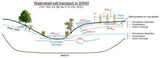
Figure 1Schematic showing a cross section of an irrigated stream–aquifer system and the major transport pathways of salt, which consists of the eight major ions of SO4, Ca, Mg, Na, K, Cl, CO3, and HCO3. The concentration of each ion is also governed by equilibrium chemistry reactions such as precipitation–dissolution, complexation, and cation exchange within the soil profile and within the aquifer.
The salinity module is implemented directly in the SWAT modelling code (FORTRAN), with new subroutines developed for salt chemistry (salt_chem), salt irrigation loading (salt_irrig), salinity percolation and leaching (salt_lch), and salt groundwater transport and loading to streams (salt_gw). Other standard SWAT subroutines are modified to incorporate salt ion transport and effects, such as lagging solutes in surface runoff and groundwater flow (surfstor, substor) and routing solutes through the stream network (watqual). These subroutines are shown in Fig. 2 within the general SWAT modelling code data flow. For each day loop, the mass balance calculations for each HRU are performed. Salt subroutines are shown for chemical equilibrium, irrigation loading, salt leaching, soil salinity stress, salt groundwater transport and loading, and lagging in surface runoff and groundwater flow. At the end of the HRU calculations, the water, sediment, nutrients, and salt ion mass are routed through the stream network, with the in-stream concentration of each salt ion simulated for each SWAT subbasin. Details for each salt ion process are now presented. For the equations presented, S refers to salt mass and the subscript i refers to the eight major ions. For the transport equations, calculations are similar to SWAT's transport equations for nitrate. Salinity module input data and output data will also be discussed later in this section.
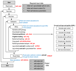
Figure 2Data flow within the SWAT-Salt modelling code. Boxes and text in black and blue indicate original SWAT loops and subroutines. Text in red indicates either new or modified subroutines for the salinity module. The required input data for the salinity module are shown in the upper shaded box, whereas the generated output files are shown in the lower shaded box.
2.2.1 Salt in surface runoff (“salt_lch” and “surfstor” subroutines)
The mass of each salt ion can be transferred from an HRU to the subbasin channel via surface runoff. The salt ion mass generated in surface runoff (kg ha−1) for the current day is calculated as
where is the salinity percolation coefficient, is the concentration of the ith salt ion in the mobile water for the top 10 mm of the soil (kg salt ∕ mm water), and Qsurf is the surface water generated from the HRU on a given day (mm water). As only a portion of the surface runoff and lateral flow reaches the subbasin channel on the day it is generated, SWAT uses a storage feature to surface runoff. The salt ion mass reaching the subbasin channel on the current day via surface runoff is calculated as
where Si, surf is the mass of the ith salt ion that reaches the subbasin channel on the current day (kg ha−1), Si, surfstor is the salt ion surface runoff stored or lagged from the previous day (kg ha−1), surlag is the surface runoff lag coefficient, and tconc is the time of concentration for the HRU (h).
2.2.2 Salt in lateral flow (“salt_lch” and “substor” subroutines)
The salt ion mass generated in lateral flow (kg ha−1) from a soil layer for the current day is calculated as
where Qlat, ly is the water discharge from the layer by lateral flow (mm water). Similar to surface runoff, only a portion of the lateral flow will reach the subbasin channel on the day it is generated, and thus the salt ion mass reaching the channel on the current day (kg ha−1) via lateral flow is calculated as
where Si, latstor is the salt ion mass stored or lagged from the previous day (kg ha−1) and TTlat is the lateral flow travel time (days).
2.2.3 Salt in soil percolation (“salt_lch” subroutine)
The salinity module tracks the mass of each salt ion (kg ha−1) in each soil layer. The salt ion mass moved to the underlying soil layer by percolation (kg ha−1) is calculated as
where Qperc, ly is the amount of water percolating to the underlying soil layer on a given day (mm water). After percolation has been simulated, the concentration of each salt ion (mg L−1) in each soil layer is calculated using the area (m2) of the HRU and the volume of water in the soil layer (m3). The leached salt ion mass is added to the shallow aquifer using the following:
where Si, rech is the salt ion mass loaded to the water table via recharge (kg ha−1), Si, perc is the salt ion mass percolated from the bottom layer of the soil profile, is the leached salt ion mass from the previous day, and gwdelay is the groundwater delay time, i.e., the time required for water leaving the bottom of the root zone to reach the water table (days).
2.2.4 Salt in groundwater flow (“salt_gw” subroutine)
The salinity module tracks the mass of each salt ion (kg ha−1) in the aquifer. The salt ion mass generated in groundwater flow (kg ha−1) from the aquifer for the current day is calculated as
where is the salt ion concentration in the aquifer (kg salt ∕ mm water) and Qgw is the groundwater flow generated for the HRU for the current day (mm water). The concentration of each salt ion in each HRU aquifer is calculated on each day by dividing the total mass of the salt ion (g) by the total volume of groundwater (m3).
2.2.5 Salt in streamflow (“watqual” subroutine)
Water is routed through the watershed channel network using the variable storage routing method, a variation of the kinematic wave model (Neitsch et al., 2011). The mass of each salt ion is routed through the channel network with water, with no chemical reactions changing in-stream salt ion concentration. Similar to any constituent in SWAT, salt ion loadings (kg d−1) can be specified for any subbasin reach of the watershed.
2.2.6 Salt in irrigation water (“salt_irrig” subroutine)
Salt ion mass is added to the soil profile via irrigation water, with water derived from either the aquifer (groundwater pumping) or from surface water diversions. Including constituent mass in irrigation water is a new feature for SWAT, as the original code does not account for nutrient (N, P) mass in irrigation water. If the irrigation water source is a subbasin reach (surface water irrigation), the concentration of each salt ion is multiplied by the volume of applied irrigation water (depth of water ⋅ HRU area) to determine the mass of each salt ion (kg ha−1) to add to the first soil layer. If the irrigation water source is the shallow aquifer, the concentration of each salt ion in the HRU aquifer is used to estimate salt loading to the first soil layer. The salt ion mass is then removed from the HRU aquifer.
2.2.7 Salt solution chemistry
The salinity chemistry implemented in SWAT is based on the Salinity Equilibrium Chemistry (SEC) module developed for soil–aquifer systems (Tavakoli-Kivi et al., 2019). The equations for salinity solution chemistry presented here are performed for each HRU soil layer and for each HRU. The solution chemistry in this module is similar to that implemented in other water chemistry models (UNSATCHEM: Šimůnek et al., 2012, PHREEQC: Parkhurst and Appelo, 2013, MINTEQA2: Paz-Garcia et al., 2013). Thus, only basic details are presented here.
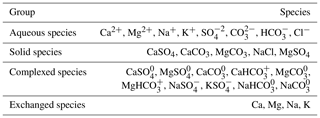
The SEC module includes 8 aqueous components, 10 complexed species, 5 solid (salt mineral) species, and 4 exchange species (Table 1). The eight aqueous components (, Ca2+, Mg2+, Na+, K+, Cl−, , ) are included due to their presence in the majority of soil–aquifer systems. The five salt minerals (CaSO4, CaCO3, MgCO3, NaCl, MgSO4) are also included due to their presence in many soil–aquifer systems, although the module can be amended to include any mineral species. The module simulates the dissolved concentration (mg L−1) of the eight ions in soil water and groundwater and the solid mass concentration of the five salt mineral species in the soil and the aquifer sediment according to precipitation–dissolution, complexation, and cation exchange reactions.
For these calculations, the duration of the model time step (daily time step for SWAT) is assumed long enough for all constituent reactions to achieve equilibrium. The concentration of species at equilibrium is calculated using a stoichiometric algorithm approach, in which mass balance and mass action equations are solved simultaneously. This method is used in other water chemical equilibrium packages such as PHREEQC (Parkhurst and Appelo, 2013) and MINTEQA2 (Paz-Garcia et al., 2013).
Law of mass action
At equilibrium, the concentrations of all reactants and products are related using the equilibrium constant K:
where A and B are reactants, C and D are products, a, b, c, and d are constants, and the parentheses denote solute activities. The activity of the ith solute, iA, is computed by multiplying the activity coefficient γi by the molal concentration, where γi depends on the ionic strength I of the solution:
where zi is the charge number of the ith ion and mi is the molality (mol ∕ kg H2O). γi is then given as
where Aa and Ba are temperature-dependent constants (Aa=0.5085 m−1 and m−1 at 25 ∘C) and ai is a measure of the effective diameter of a hydrated ion i. The first equation in (10) is the Debye–Hückel equation for dilute solutions, and the second equation is the Davis equation.
Mass balance equations
The mass of each element in the system, either in ion or complexed form, is tracked by a set of mass balance equations. Equations for SO4, Cl, Ca, and Na are
where T denotes total concentration and brackets indicate species' molality. Similar equations are written for Mg, K, CO3, and HCO3.
Precipitation–dissolution reactions
Salt minerals (ABs) can dissolve or precipitate according to the stoichiometric reaction
The salt mineral will dissolve if the solution is under-saturated in regards to and , and will precipitate if the solution is super-saturated. Salt minerals in the SEC module include CaSO4, CaCO3, MgCO3, MgSO4, and NaCl, due to their common occurrence in aquifers. For example,
with a solubility product constant
Within the SEC module, minerals are added to the system one at a time, with the solubility limits of each mineral used to determine the direction of each reaction (precipitation or dissolution).
Complexation reactions
Based on the law of mass action, equilibrium equations are written for all complexed species. For example, the equation for is
where K is the equilibrium constant and is equal to 0.004866.
Cation exchange reactions
Cation exchange is calculated to determine the sorbed and released ions from sediment surfaces to the solution. The order of replaceability is Na > K > Mg > Ca, determined by Coulomb's law. The cation reaction as an equivalent reaction is represented by the Gapon equation:
where X1∕mM is exchangeable cation M on the surface (meq 100 g−1), X1∕nN is exchangeable cation N on the surface (meq 100 g−1), M and N are metal cations, and m+ and n+ are the charges of cations M and N, respectively. Using the cation exchange capacity of the soil and a coefficient of the Gapon selectivity coefficient for each reaction, the concentration of each exchangeable species is determined.
The salinity chemistry reactions (precipitation–dissolution, complexation, cation exchange) are simulated for each HRU within the salt_chem subroutine (see Fig. 2). Within this subroutine, the chemistry reactions are applied to the current simulated concentration values of the five salt minerals and the eight salt ions for each soil layer and aquifer, to calculate new concentration values. These new concentration values are then used to simulate salt leaching (salt_lch subroutine) and salt ion loading in surface runoff (surfstor) and groundwater flow (salt_gw, substor) (Fig. 2). At the end of each daily time step, the simulated salt ion mass (kg) in each transport pathway (irrigation, leaching, runoff, percolation, lateral flow, groundwater flow, dissolution/precipitation) is stored for mass balance assessment and output.
2.2.8 Salinity module input/output
Required data for running the SWAT salinity module include precipitation–dissolution solubility products for the five salt minerals (CaSO4, CaCO3, MgCO3, NaCl, MgSO4), initial concentration of salt ions in soil water and groundwater, and initial salt mineral solid concentration (% of bulk soil) in soil and aquifer sediment. Initial concentrations are required for each HRU. However, as will be shown in the “Scenarios and model guidelines” section, using uniform (i.e., each HRU given the same value) concentration values yields the same result as using spatially variable initial concentrations if a warm-up period of several years is used in the SWAT simulation.
All input data are provided in the “salt_input” file. To turn on the salinity module, a single line has been added to the end of the file.cio file, with a flag (0 or 1) being read to exclude or include the salinity module. If the flag is set to 1, the SWAT code will open and read the contents of the salt_input file.
Four output files contain simulated salt ion data for the watershed (Fig. 2):
-
salt.output.std contains the total salt mass (TDS) transported via lateral flow, groundwater flow, surface runoff, tile drains, percolation, irrigation of surface water, irrigation of groundwater, upflux water, and dissolution, normalized to the area of the watershed (kg ha−1).
-
salt.output.rch contains the loading (kg) and concentration (mg L−1) of each salt ion for each subbasin channel, for each day of the simulation. Results from this file can be used to plot time series of salt ion concentration, as shown in the “In-stream salt ion concentration” section.
-
salt.output.sub contains the total salt mass (TDS) transported via lateral flow, groundwater flow, surface runoff, tile drains, percolation, irrigation of surface water, irrigation of groundwater, and dissolution for each subbasin, for each day of the simulation. The salt loads (kg ha−1) are normalized to the subbasin area.
-
salt.output.hru contains salt ion concentration in the soil water and in the groundwater for each HRU, for days specified in the salt_input file.
3.1 Study region: Lower Arkansas River Valley, Colorado
The salinity module is tested for a 732 km2 irrigated stream–aquifer system along the Arkansas River in southeastern Colorado (Fig. 3a). The region consists of the Arkansas River and tributaries (e.g., Timpas Creek, Crooked Arroyo; see Fig. 3a) running through and over a thin (∼10–15 km in width) and shallow (∼10–20 m) sandy alluvial aquifer. The climate is semi-arid, requiring irrigation to supplement rainfall for crop growth. Irrigation water is derived either from the Arkansas River via a system of irrigation canals or from the aquifer via a network of ∼500 pumping wells (Fig. 3a). Cultivation and associated irrigation occur from March through November.
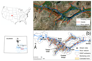
Figure 3Map of the study region within the Lower Arkansas River Valley of Colorado, showing (a) the Arkansas River and tributaries, irrigation canals, and pumping wells, and (b) cultivated fields, monitoring wells where groundwater is sampled for salt ions, sampling sites where surface water is sampled for salt ions, and SWAT subbasins.
Salinization of soil, groundwater, and surface water in the region has steadily worsened since the 1970s due to increased irrigation diversions from the Arkansas River, high water tables due to excessive water applications to fields, and the existence of salt minerals, particularly gypsum (CaSO4) (Konikow and Person, 1985; Goff et al., 1998; Gates et al., 2002, 2016). Soil salinity levels under about 70 % of the area exceed the threshold tolerance for crops, with the regional average of crop yield reduction from salinity and waterlogging estimated to range from 11 % to 19 % (Gates et al., 2002; Morway and Gates, 2012).
From sampling groundwater from a network of 82 observation wells (see Fig. 3b) (sampling from June 2006 to May 2010), the average salinity concentration of shallow groundwater is approximately 2700 to 3000 mg L−1, and annual salt loading to the Arkansas River from groundwater return flows is about 500 kg per irrigated hectare, per kilometer of the river. In the 1990s, 68 % of producers stated that high salinity levels are a significant concern (Frasier et al., 1999). For the region modelled in this study, average TDS concentration (CTDS) in groundwater is 3334 mg L−1 (443 samples), with a minimum of 459 mg L−1 and a maximum of 44 600 mg L−1. The presence of gypsum is revealed in the high concentration of SO4 (), with average, minimum, and maximum concentrations of 1878, 147, and 29 457 mg L−1, respectively. Average soil water salinity, based on electrical conductivity of a soil paste extract (ECe), is 4.11 dS m−1 (54 700 measurements), with a minimum and a maximum of 0.9 and 56.5 dS m−1, respectively (Morway and Gates, 2012). These values were estimated from measurements of apparent bulk soil conductivity, taken with a Geonics EM-38 electromagnetic induction sensor, as described in Morway and Gates (2012). Surveys were performed during the months of March–September for 1999–2005. Based on six surface water sampling sites (four in the Arkansas River, two in tributaries; Fig. 3b), average CTDS and are 1145 and 560 mg L−1, respectively. More details of observed groundwater, soil water, and surface water concentrations are provided in Sect. 3.3.2 when model results are presented.
3.2 SWAT model
A previously calibrated and tested SWAT model for the study region is used to simulate salt fate and transport using the developed salinity module. The SWAT model is detailed in Wei et al. (2018). The region was divided into 72 subbasins (see Fig. 3b). The digital elevation model (DEM), stream network, soil map, land-use map, climate data, streamflow, and canal diversion data were obtained from the USGS, NRCS, and several state agencies, as summarized in Wei et al. (2018). A method was developed to apply SWAT to highly managed irrigated watersheds, and included designating each cultivated field as an individual HRU (see Fig. 3b for the map of fields), crop rotations to simulate the effects of changing crop types for each field during the 11-year simulation, seepage to the aquifer from the earthen irrigation canals, and SWAT's auto-irrigation algorithms to trigger irrigation events based on plant water demand for both surface water irrigation and groundwater irrigation. The method resulted in 5270 HRUs. Implementing canal seepage required a slight change to the SWAT modelling code to add pre-processed, estimated canal seepage to the HRU aquifer. Canal seepage rates were obtained from field measurements (Susfalk et al., 2008; Martin et al., 2014).
The model was run for the 1999–2009 time period, with simulated streamflow compared to observed hydrographs at five stream gages (Rocky Ford, La Junta, Las Animas, Timpas Creek, Crooked Arroyo; see Fig. 3b) for model testing (Wei et al., 2018). Calibration was performed using SWAT-CUP (Abbaspour et al., 2008) using the observed streamflow at the Rocky Ford, Las Animas, and Timpas Creek stations. Twenty parameters were targeted for modification during the calibration process, with the following exhibiting strong control on streamflow: SCS runoff curve number, Manning's n value for the main channel, effective hydraulic conductivity of the channel, initial volume of groundwater, recharge delay time, fraction of deep aquifer percolation, and snowfall temperature. Further details regarding calibration, model implementation, and hydrologic results are found in Wei et al. (2018).
3.3 SWAT model with salinity module
3.3.1 Model construction and simulation
The SWAT model with the new salinity module is run from 1 April 1999 to 13 December 2009, with observed data for testing available from June 2006 to December 2009. The 1999–2005 period thus serves as a warm-up simulation period. The calibration period is 2006–2007, and the testing period is from 2008 to 2009. Required inputs include initial soil water and groundwater ion concentrations, initial soil and aquifer sediment salt mineral fractions, and, due to the study region being a part of the larger Lower Arkansas River Valley, ion mass loading in the Arkansas River at the upstream end of the modelled region (Catlin Dam; see Fig. 3b).
Salt ion mass loadings (kg d−1) in the Arkansas River at Catlin Dam were estimated using daily measured values of EC (dS m−1) and streamflow (m3 s−1) and periodic measurements of salt ion concentration (mg L−1). Linear relationships were established between EC and the concentration of each salt ion, with this relationship then used to estimate salt ion concentration for each day of the simulation period. The daily in-stream mass of each salt ion was then calculated by multiplying daily salt ion concentration by streamflow and added to the point-source SWAT input file for the appropriate subbasin. Figure 4a shows the daily loading (kg d−1) for each salt ion using this method. The make-up of total mass loading by salt ions is shown in Fig. 4b, with SO4 accounting for 47 % of total in-stream salt mass. The linear relationship between EC and selected salt ions (SO4, Cl, Na) and TDS is shown in the charts along the bottom of Fig. 4. For TDS the R2 value of the relationship is approximately 0.93.
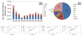
Figure 4Data summarizing the specified loading of salt (kg d−1) at the Catlin Dam gage site, using observed EC (dS m−1) and stream discharge (m3 d−1) data: (a) daily loading of salt ion, (b) percentage of total salt loading attributed to each salt ion, and (bottom charts) example regression plots used to relate EC to salt ion concentration.
Initial salt ion concentrations in soil water and groundwater were based on averages of observed groundwater concentrations. For the baseline simulation, the same values were assigned to each HRU. These are 1875, 330, 175, 440, 10, 150, 5, and 350 mg L−1 for , CCa, CMg, CNa, CK, CCl, , and , respectively. The effect of using spatially varying initial concentrations is explored in additional scenarios. Salt mineral fractions for CaSO4 and CaCO3 in the HRU soil layers are based on a soil survey of the region from the Natural Resources Conservation Service (NRCS). The fraction of soil that is CaSO4 and CaCO3 was set to 0.1 and 0.01, with all others set to 0.0. For the aquifer sediment, fractions are based on the spatial patterns determined in Tavakoli-Kivi et al. (2019) for a salinity groundwater transport study of the same region. Solubility products for precipitation–dissolution of salt minerals were obtained from the literature and from Tavakoli-Kivi et al. (2019) and are , , , 0.0072, and 37.3 for CaCO3, MgCO3, CaSO4, MgSO4, and NaCl, respectively, for both soil and aquifer sediments.
Manual calibration was applied to the model to yield correct magnitudes of salt ion concentration in soil water, groundwater, and stream water. Due to the predominance of SO4 and Ca among salt ions in the regional system, targeted parameters were the solubility product of CaSO4 precipitation–dissolution and the soil fraction of CaSO4. The solubility product was increased from 0.000049 to 0.0003, and the soil fraction of CaSO4 was decreased from 0.01 to 0.009. Model results are tested against in-stream concentration of salt ions, soil salinity, groundwater concentration of salt ions, and groundwater salt ion mass loading to the Arkansas River. For soil salinity, model results are compared with the 54 700 ECe values from the field survey. ECe of the soil water in the SWAT model layers for each day of the simulation is estimated using the following steps: (1) soil water TDS is computed by summing up salt ion concentrations in the soil water; (2) soil water EC (ECw) is computed by dividing soil water TDS by a TDS → ECw (dS m−1) conversion of 1020 (mg L−1 per dS m−1) based on soil water samples; and (3) ECe is computed by multiplying ECw by the ratio of stored water (mm) to water at saturation (mm) for the SWAT soil layer. Simulated ECe values are included in the comparison with field-measured ECe values if the simulated water content of the HRU soil layer is greater than 0.07, since Morway and Gates (2012) measured field ECe only if the soil water content was above this value due to EM-38 sensors being unreliable at low water contents (Rhoades et al., 1999).
Several variations of the model were run to test the effect of (1) initial salt ion concentrations in the HRU soil layers and (2) specified loading of salt ion mass at the upstream end of the Arkansas River. For (1), the variations include uniform initial concentrations (baseline model), random spatially variable concentrations, and initial concentrations equal to 0. For (2), the variation included one simulation with no loading.
3.3.2 Model results
In-stream salt ion concentration
Simulated and observed in-stream salt ion concentrations (mg L−1) are shown in Fig. 5 for the Rocky Ford, Timpas Creek, Crooked Arroyo, and Las Animas sites for each of the eight ions. Overall, the model tracks the measured concentrations well, particularly for SO4, Ca, and HCO3. Results for TDS at all five gaging stations are shown in Fig. 6, including the Nash–Sutcliffe model efficiency coefficient (NSE) for each site. NSE values are good for Rocky Ford and Crooked Arroyo (0.68 and 0.65) and poor for the other three (<0.3). However, comparing simulated and measured in-stream concentrations on a daily basis is generally a difficult challenge for watershed modelling.
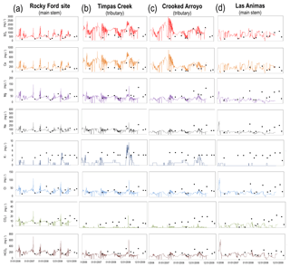
Figure 5Time series of simulated and observed concentrations (mg L−1) for each of the eight major salt ions for the (a) Rocky Ford site, (b) Timpas Creek site, (c) Crooked Arroyo site, and (d) Las Animas site. Simulated hydrographs for these sites are in Wei et al. (2018).
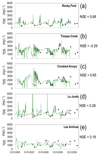
Figure 6Simulated and observed total dissolved solids (TDS) (mg L−1) in the five stream sampling sites along the Arkansas River (a, d, e) and two tributaries (b, c). See Fig. 3 for locations. TDS is the summation of the concentration of the eight salt ions. The Nash–Sutcliffe model efficiency coefficient (NSE) is shown for each plot.
In the two tributaries (Timpas Creek and Crooked Arroyo) and the watershed outlet (Las Animas), the model tends to under-predict the ions of low concentration: Mg, K, Cl, and CO3. The cause of the under-prediction of these ions may be due to the unobserved presence of MgSO4, MgCO3, and NaCl in the soil. These minerals are not observed in NRCS soil surveys of the region and hence were not included in the baseline model. However, several model scenarios were run to investigate the influence of these minerals. Soil bulk fractions between 0.0001 and 0.0005 were applied for these three minerals, with a large resulting effect on in-stream concentrations of Mg, Na, Cl, and CO3. For example, using a fraction of 0.0002 resulted in correct magnitude of these four ions at the Las Animas site but over-estimated concentrations in the tributaries (e.g., Timpas Creek) (Fig. 7). This model scenario, however, applied uniform salt mineral fractions of MgSO4, MgCO3, and NaCl across all 5270 HRUs. Applying spatially varying fractions across the watershed could provide the correct magnitude of in-stream concentrations of all ions at all stream sampling sites. Regardless, measured in-stream concentrations can provide key information as to the salt minerals present in the watershed, and differences between model output and field data highlight the need for better field survey data of salt mineral content in soils.
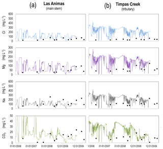
Figure 7Time series of simulated and observed concentrations (mg L−1) for each of the eight major salt ions for the (a) Las Animas site and (b) Timpas Creek site, for the model scenario of using 0.0002 soil bulk fractions for MgCO3, MgSO4, and NaCl. For the baseline model, these fractions were set to 0.00.
The in-stream concentrations in the two tributaries (Fig. 5b, c) are much more variable than the two sites in the main stem of the Arkansas River. The two tributaries act as drainage channels for irrigation runoff and groundwater return flows, with much lower flows than the Arkansas River, and hence the in-stream concentrations are affected much more strongly by salt loadings from irrigation events and associated flow patterns. In regards to the NSE, the model under-performs for the tributaries (Timpas Creek, Crooked Arroyo), with NSE equal to −0.29 and 0.65, respectively, for TDS (Fig. 6b, c). However, the overall trends and magnitude compare well to observed data. This is shown in the 1:1 plot of all salt ion data for Timpas Creek in Fig. 8b, resulting in an R2 value of 0.69. The relationship for Crooked Arroyo yields an R2 value of 0.80 (not shown). This is particularly promising given that there is no specified upstream loading for the tributaries, and hence all salt mass within the stream system is due to surface runoff, lateral flow, and groundwater discharge. Hence, comparing simulated and observed in-stream salinity concentrations in these two systems provides a strong test for the model.
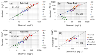
Figure 8Log–log plots of observed vs. simulated salt ion concentration for the (a) Rocky Ford, (b) Timpas Creek, and (c) Las Animas surface water sampling sites. (d) shows the comparison of TDS for the five sites.
The summary of in-river salt concentration results is shown by a 1:1 comparison of all salt ion data for the Rocky Ford (Fig. 8a) and Las Animas (Fig. 8c) sites, which yield R2 values of 0.87 and 0.66, respectively. Timpas Creek (Fig. 8b) has an R2 value of 0.69. However, as the SWAT model often is used to estimate monthly in-stream loads rather than daily in-stream concentration, these results are promising regarding the use of SWAT to estimate in-stream salinity loadings.
Figure 9 shows the salt loading via the hydrologic pathways of groundwater discharge (Fig. 9a), surface runoff (Fig. 9b), and percolation from the soil profile to groundwater (Fig. 9c). For Timpas Creek, 96 % of salt in the creek water is from groundwater discharge, 3 % from surface runoff, and 1 % from lateral flow. For Crooked Arroyo, the portions are 91 %, 6 %, and 3 %, and for the Arkansas River they are 96 %, 3 %, and 1 %, highlighting the strong influence of groundwater on surface water salt load. This is shown further by examining the domain-wide salt balance, presented in the “Salt balance” section. The mass loading of total salt from the aquifer to the Arkansas River for each day of the 2006–2009 time period is shown in Fig. 10. Mass balance plot values are the mean of a stochastic river mass balance calculation of surface water salinity loadings along the length of the Arkansas River within the model domain, using a method similar to Mueller-Price and Gates (2008), with values indicating the mass of salt not accounted for by surface water loadings. These unaccounted-for loadings include groundwater and thus provide an upper limit of in-stream salt loading from groundwater discharge.
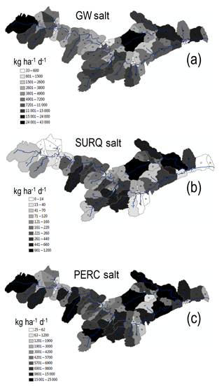
Figure 9Average daily loading (kg ha−1) of salt by subbasin to (a) stream network via groundwater discharge, (b) stream network via surface runoff, and (c) groundwater via soil percolation.
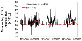
Figure 10Simulated daily mass loading of TDS (kg) to the Arkansas River via groundwater discharge for the SWAT model with uniform initial salt concentrations. Results from a salt mass balance calculation on the Arkansas River are also plotted, showing the unaccounted-for TDS loadings (groundwater, surface runoff, small inflows) in the Arkansas River.
Groundwater and soil water salinity
Groundwater salt results are shown by spatial maps and by comparison of frequency distributions. For all simulated results, only concentration values from days on which field samples were taken are included in the analysis. Time-averaged TDS (mg L−1), SO4 (mg L−1), and Na (mg L−1) in groundwater are shown for each HRU in Fig. 11. Also shown are soil water EC (dS m−1) for each HRU soil profile and the percent of the soil profile (Fig. 11e) and aquifer (Fig. 11f) that is CaSO4 (solid mineral) at the end of the simulation period. These maps are shown to provide an indication of the degree of spatial variation simulated by the model. Variation in each system response is large, with TDS ranging from 0 to ∼11 700 mg L−1, SO4 from 0 to ∼6700 mg L−1, and Na from 0 to ∼1270 mg L−1. In comparison, if data from an outlier monitoring well are excluded (monitoring well with salinity values more than double those of any other monitoring well), the maximum observed values for TDS, SO4, and Na are 13 000, 6500, and 2600 mg L−1.
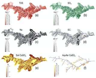
Figure 11HRU average concentration over the 2006–2009 simulation period for (a) groundwater TDS (mg L−1), (b) groundwater SO4 (mg L−1), (c) groundwater Na (mg L−1), and (d) soil water electrical conductivity EC (dS m−1). (e) and (f) show percentage of soil bulk volume and aquifer bulk volume, respectively, that is CaSO4, near the end of the simulation in May 2010.
Results for all salt ions are summarized in Table 2. Average concentration of field samples (based on field samples from 82 monitoring wells shown in Fig. 3b) and HRU-simulated groundwater salinity compares well, particularly for SO4 (1878 to 2149 mg L−1) and for TDS (3334 to 3508 mg L−1). In addition to a comparison of maximum and average values, comparison at various magnitude levels is performed using relative frequency plots shown in Fig. 12. Results for SO4 (Fig. 12a), HCO3 (Fig. 12b), and TDS (Fig. 12c) are shown. Similar to the results shown in Table 2, the comparison for SO4 and TDS is good, but the model generally under-predicts HCO3 for most HRUs.
Table 2Summary statistics for observed (monitoring well) and simulated (SWAT) salinity concentrations in groundwater.
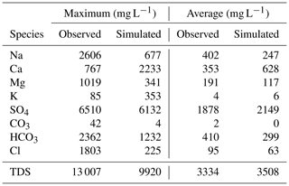
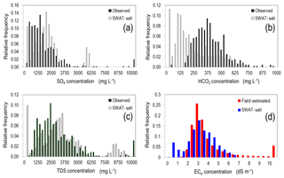
Figure 12Relative frequency plots of simulated and observed values of (a) SO4 groundwater concentration, (b) HCO3 groundwater concentration, (c) TDS groundwater concentration, and (d) ECe soil water concentration of a saturated paste. Groundwater-simulated values are taken from each HRU of the SWAT simulation, on days for which observed values are available. For soil ECe, values are taken only from HRUs that coincide with cultivated fields.
A relative frequency plot of observed and simulated ECe (dS m−1) in the soil profile is shown in Fig. 12d. The simulated values were taken from HRUs coinciding with cultivated fields for the days of 15 April, 15 May, 15 June, 15 July, and 15 August, for the years 2001–2005. Note that simulated values were taken from each cultivated HRU, whereas the field surveys using the EM-38 sensors were conducted in approximately 100 fields. The average of observed values is 4.1 dS m−1, although this number is skewed by extremely high values (>30 dS m−1). If only values <6.5 dS m−1 are considered (89 % of the samples), then the average is 3.2 dS m−1. The average of the simulated values is 2.96 dS m−1. As seen from the frequency distribution in Fig. 12d, the model tends to under-estimate soil salinity for some of the HRUs and does not capture the high salinity values (>7 dS m−1). However, the overall magnitude and distribution of values approach the distribution of the measured values. Note that EM-38 measurements have inherent uncertainty. In addition, some of the HRUs included in the analysis are fallow during this period (2002–2005), which may lead to low soil salinity values that were not measured in the field survey.
Salt balance
The domain-wide salt balance is presented in Fig. 13a. All salt balance components are included, with all values scaled according to the small salt flux (lateral flow =1 unit). For the soil profile, salt is added via groundwater irrigation (17 units), surface water irrigation (29), dissolution of salt minerals (97), and upflux from the aquifer-saturated zone (44), and removed via percolation (134), surface runoff (3), and lateral flow (1). A similar salt balance can be performed for each salt ion in the system. Salt removed from the aquifer and added to the soil profile via upflux is approximately 30 % of percolation, which compares well to a comparison of water upflux and recharge magnitudes computed by Morway et al. (2013) in a groundwater modelling study of the region using MODFLOW.
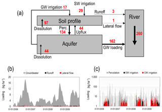
Figure 13Magnitude of salt balance components in the watershed model for TDS, showing (a) relative salt flux between soil storage compartments in the watershed for each salt transport pathway; (b) daily loading (kg ha−1) of salt in groundwater, surface runoff, and lateral flow to streams; and (c) daily loading (kg ha−1) of salt in percolation water (from the bottom of the soil profile to the aquifer), irrigation derived from irrigation canals, and irrigated derived from groundwater pumping.
Of the salt entering the river, 97.6 % is from groundwater (162 units out of 166) and the rest from surface runoff and lateral flow. A time series of daily loading (kg ha−1) for these three components is shown in Fig. 13b, and loadings for percolation, surface water irrigation, and groundwater irrigation are shown in Fig. 13c, showing the seasonal trends in applying irrigation water. Notice that the highest groundwater loading rates coincide with the “spikes” in the in-stream concentration plots of Figs. 5 and 6, indicating the strong influence of groundwater loading on in-stream salt concentrations. The fluctuations in simulated in-stream concentration, however, are larger than observed with the measured values. This is due to the manner in which SWAT simulates groundwater return flow, with a steady-state flow equation for each HRU that provides pulses of groundwater to streams rather than the multi-dimensional groundwater flow equation that provides physically based, spatially distributed diffuse flow through the aquifer towards the stream network.
Results in Fig. 13c indicate that much of the salt leaching from the soil profile is due to dissolution of salt minerals. Results also indicate the importance of including salt mass in applied irrigation water, as it accounts for approximately half of salt leaching to the aquifer. Finally, results show the importance of including precipitation–dissolution in the module, as this process is a large component of the salt balance. Without including this process, the module would severely under-predict salt ion concentrations throughout the watershed, demonstrating the need to include each salt ion individually as opposed to modelling salinity as a conservative solute in the system.
Scenarios and model guidelines
The effect of initial salt ion concentrations and upstream salt ion mass loading is summarized by the time series charts in Fig. 14. For the Rocky Ford and Las Animas gaging sites, a time series of simulated TDS (mg L−1) is compared for the following scenarios: uniform initial salt ion concentration (“Original”: this refers to the baseline simulation); HRU-variable initial concentration (“Variable IC”); initial concentrations equal to 0 (“Zero IC”); and not accounting for upstream salt ion mass loading at Catlin Dam (“No US Loading”). There are only small differences between using uniform or HRU-variable initial concentrations for soil water and groundwater. Any differences are readily resolved during the warm-up period. Hence, to facilitate model use we recommend that uniform initial concentrations be used.
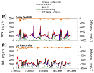
Figure 14Simulated in-stream TDS concentration (mg L−1) at the Rocky Ford and Las Animas gage sites along the Arkansas River for four scenarios: uniform initial conditions (IC) of salt soil water and groundwater concentrations, corresponding to the original simulation; variable IC; IC =0; and no upstream loading of salt at the Catlin Dam site. Also shown is the difference between the IC =0 scenario and the original scenario.
Using initial concentrations equal to 0 mg L−1 has a significant effect, particularly for downstream sites such as Las Animas (Fig. 14c, d). For this watershed, salt loading to the streams is principally from groundwater, and if soil water and groundwater are not provided with initial salt ion concentrations, the groundwater salt ion loading to subbasin streams is small compared to the baseline simulation. As downstream flow and in-stream salt loading are affected by groundwater loading, these areas (e.g., Las Animas site) experience the effect more acutely than upstream sites such as Rocky Ford (Fig. 14a, b). However, by the end of the simulation (2009), the difference between “Zero IC” and “Original” is small. This is shown by the “Diff” time series for each plot. Therefore, if groundwater discharge is a large component of total water yield for the watershed, “Zero IC” should not be used or a long warm-up simulation period needs to be used.
Not including upstream salt ion loading at Catlin Dam has a stronger effect on the Rocky Ford site (Fig. 14a, b) than at the outlet (Las Animas) (Fig. 14c, d). This is due to Las Animas being much farther downstream, and hence there is much more groundwater salt ion loading to the streams that can make up for the salt not included at the upstream end of the Arkansas River at Catlin Dam. Overall, any point sources of in-stream salt should be added, unless only downstream areas are targeted for baseline simulations and best management practice investigation. The effect of neglecting point sources of in-stream salt decreases as the groundwater loading component of total salt yield increases.
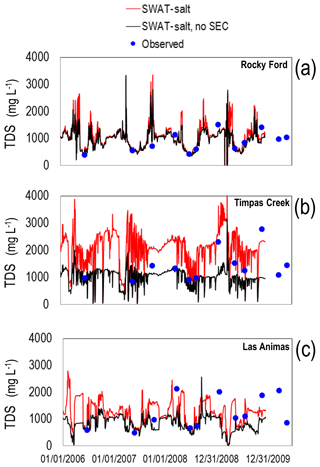
The importance of including equilibrium chemistry in the salt transport module is demonstrated by the results shown in Fig. 15. The simulated in-stream TDS (mg L−1) is shown at the Rocky Ford site (Fig. 15a), the Timpas Creek site (B), and the Las Animas site (C), for both the original simulation (red line) and a simulation “No SEC” that does not include the SEC module (black line). The “No SEC” simulation therefore represents a system wherein salt is transported through the stream–aquifer system as a conservative species. Clearly, in-stream concentrations are much too low for the simulation without the SEC module for the Timpas Creek and Las Animas sites. This is due to the neglect of salt mineral dissolution, which in the actual system transfers salt mass from the soil and aquifer material to soil water and groundwater, thereby increasing the loading of salt to the stream network. For the Rocky Ford site, the scenarios yield similar results due to the location of the site being close to the upstream end of the modelled region, and thus in-stream concentrations are not affected by groundwater and surface runoff salt loadings to the river. For this system, and likely most watersheds, equilibrium chemistry must be included to establish the correct magnitude of salt loading and concentrations.
3.3.3 Model use and limitations
The salinity module of SWAT differs from other salinity models in that it accounts for salt loading for each major hydrologic pathway in a watershed setting (stream, groundwater, lateral flow, surface runoff, tile drain flow), for each major salt ion, subject to chemical equilibrium reactions (precipitation–dissolution, complexation, cation exchange). As such, it can be used to estimate baseline salt loading within a watershed and also explore the impact of land management and water management scenarios to mitigate soil salinity, groundwater salinity, and surface water salinity. The model, however, does not simulate physically based, spatially distributed groundwater flow and solute transport with an accurate depiction of water table elevation and groundwater head gradient, and thus the trends in groundwater salt loading to streams may not be accurate (see Fig. 9). To overcome this issue, the new salinity module could be incorporated into SWAT-MODFLOW (Bailey et al., 2016), which links SWAT and MODFLOW to simulate land surface and subsurface flow processes, and SWAT-MODFLOW-RT3D (Wei et al., 2018), which includes reactive transport of solutes into SWAT-MODFLOW.
This study presents a new watershed-scale salt ion fate and transport model by developing a salinity module for the SWAT model. The module accounts for salt loading for each major hydrologic pathway in a watershed setting (stream, groundwater, lateral flow, surface runoff, tile drain flow), for each major salt ion (SO4, Ca, Mg, Na, K, Cl, CO3, HCO3). The module also accounts for principal equilibrium chemistry reactions (precipitation–dissolution, complexation, cation exchange). For precipitation–dissolution, five salt minerals (CaSO4, CaCO3, MgCO3, NaCl, MgSO4) have been included. The model was applied and tested in a 732 km2 irrigated stream–aquifer watershed in southeastern Colorado, along the alluvial corridor of the Arkansas River. Model results are tested against in-stream salt ion concentration, groundwater salt ion concentration, soil salinity, and groundwater salt loading to the Arkansas River.
The model can be used to assess baseline salinity conditions in a watershed and to explore land and water management strategies aimed at decreasing salinization in river basins. Such strategies may include on-farm management, lining irrigation canals to reduce saline canal seepage, dry-drainage practices, and reduction of volumes of applied irrigation water. Due to the simulation of soil water salt ion concentrations and SWAT's simulation of crop growth, the salinity module can also be used to investigate the effect of these strategies on crop yield. Although this study applied the model to an irrigated area, the model can be applied to non-irrigated areas as well.
The code consists of the original SWAT files, with six additional files for the salinity module. All files are *.f FORTRAN files. The code is available on GitHub (https://github.com/rtbailey8/SWAT_Salinity/, Bailey, 2019). The code can also be sent via request from Ryan Bailey at rtbailey@colostate.edu.
RTB wrote the salinity module for SWAT and tested the module for the study region. STK prepared the solution chemistry algorithms for the salinity module. XW prepared and tested the original SWAT model for the study region and facilitated use of the new salinity module for the constructed SWAT model.
The authors declare that they have no conflict of interest.
The authors wish to thank two anonymous reviewers for their suggestions which greatly improved the manuscript.
This paper was edited by Christian Stamm and reviewed by two anonymous referees.
Abbaspour, K. C., Yang, J., Reichert, P., Vejdani, M., Haghighat, S., and Srinivasan, R.: SWAT-CUP: SWAT calibration and uncertainty programs, Swiss Federal Institute of Aquatic Science and Technology, Zurich, Switzerland, 2008.
Abbaspour, K. C., Rouholahnejad, E., Vaghefi, S., Srinivasan, R., Yang, H., and Klove, B.: A continental-scale hydrology and water quality model for Europe: Calibration and uncertainty of a high-resolution large-scale SWAT model, J. Hydrol., 524, 733–752, https://doi.org/10.1016/j.jhydrol.2015.03.027, 2015.
Arabi, M., Govindaraju, R. S., Hantush, M. M., and Engel, B. A.: Role of watershed subdivision on modeling the effectiveness of best management practices with SWAT, J. Am. Water. Resour. As., 42, 513–528, https://doi.org/10.1111/j.1752-1688.2006.tb03854.x, 2006.
Bailey, R.: SWAT-Salt: Source code for original SWAT model and new salt transport subroutines, available at: https://github.com/rtbailey8/SWAT_Salinity, last access: 22 July 2019.
Bailey, R. T., Wible, T. C., Arabi, M., Records, R. M., and Ditty, J.: Assessing regional-scale spatio-temporal patterns of groundwater-surface water interactions using a coupled SWAT-MODFLOW model, Hydrol. Process., 30, 4420–4433, https://doi.org/10.1002/hyp.10933, 2016.
Brown, S. C., Versace, V. L., Lester, R. E., and Walter, M. T.: Assessing the impact of drought and forestry on streamflows in south-eastern Australia using a physically based hydrological model, Environ. Earth Sci., 74, 6047–6063, https://doi.org/10.1007/s12665-015-4628-8, 2015.
Burkhalter, J. P. and Gates, T. K.: Evaluating regional solutions to salinization and waterlogging in an irrigated river valley, J. Irrig. Drain. E., 132, 21–30, https://doi.org/10.1061/(ASCE)0733-9437(2006)132:1(21), 2006.
Dechmi, F. and Skhiri, A.: Evaluation of best management practices under intensive irrigation using SWAT model, Agr. Water Manage., 123, 55–64, https://doi.org/10.1016/j.agwat.2013.03.016, 2013.
Ficklin, D. L., Luo, Y., Luedeling, E., and Zhang, M.: Climate change sensitivity assessment of a highly agricultural watershed using SWAT, J. Hydrol., 374, 16–29, https://doi.org/10.1016/j.jhydrol.2009.05.016, 2009.
Frasier, W. M., Waskom, R. M., Hoag, D. L., and Bauder, T. A.: Irrigation Management in Colorado: Survey Data and Findings, Technical Report TR99-5 Agricultural Experiment Station, Colorado State University, Fort Collins, CO, USA, 1999.
Gates, T. K., Burkhalter, J. P., Labadie, J. W., Valliant, J. C., and Broner, I.: Monitoring and modeling flow and salt transport in a salinity-threatened irrigated valley, J. Irrig. Drain. E., 128, 88–99, https://doi.org/10.1061/(ASCE)0733-9437(2002)128:2(87), 2002.
Gates, T. K., Steed, G. H., Niemann, J. D., and Labadie, J. W.: Data for Improved Water Management in Colorado's Arkansas River Basin, Hydrological and Water Quality Studies, Colorado State University, USA, 2016.
Goff, K., Lewis, M. E., Person, M. A., and Konikow, L. F.: Simulated effects of irrigation on salinity in the Arkansas River Valley in Colorado, Ground Water, 36, 76–86, https://doi.org/10.1111/j.1745-6584.1998.tb01067.x, 1998.
Haddeland, I., Heinke, J., Voß, F., Eisner, S., Chen, C., Hagemann, S., and Ludwig, F.: Effects of climate model radiation, humidity and wind estimates on hydrological simulations, Hydrol. Earth Syst. Sci., 16, 305–318, https://doi.org/10.5194/hess-16-305-2012, 2012.
Jyrkama, M. I. and Sykes, J. F.: The impact of climate change on spatially varying groundwater recharge in the grand river watershed (Ontario), J. Hydrol., 338, 237–250, https://doi.org/10.1016/j.jhydrol.2007.02.036, 2007.
Kaledhonkar, M. J. and Keshari, A. K.: Regional salinity modeling for conjunctive water use planning in Kheri command, J. Irrig. Drain. E., 132, 389–398, https://doi.org/10.1061/(ASCE)0733-9437(2006)132:4(389), 2006.
Kaledhonkar, M. J., Sharma, D. R., Tyagi, N. K., Kumar, A., and Van Der Zee, S. E. A. T. M.: Modeling for conjunctive use irrigation planning in sodic groundwater areas, Agr. Water Manage., 107, 14–22, https://doi.org/10.1016/j.agwat.2011.12.023, 2012.
Konikow, L. F. and Person, M.: Assessment of long-term salinity changes in an irrigated stream aquifer system, Water Resour. Res., 21, 1611–1624, https://doi.org/10.1029/WR021i011p01611, 1985.
Maringanti, C., Chaubey, I., and Popp, J.: Development of a multiobjective optimization tool for the selection and placement of best management practices for nonpoint source pollution control, Water Resour. Res, 45, 1–15, https://doi.org/10.1029/2008WR007094, 2009.
Martin, C. A. and Gates, T. K.: Uncertainty of canal seepage losses estimated using flowing water balance with acoustic Doppler devices, J. Hydrol., 517, 746–761, https://doi.org/10.1016/j.jhydrol.2014.05.074, 2014.
Morway, E. D. and Gates, T. K.: Regional assessment of soil water salinity across an intensively irrigated river valley, J. Irrig. Drain. E., 138, 5, 393–405, https://doi.org/10.1061/(ASCE)IR.1943-4774.0000411, 2012.
Morway, E. D., Gates, T. K., and Niswonger, R. G.: Appraising options to reduce shallow groundwater tables and enhance flow conditions over regional scales in an irrigated alluvial aquifer system, J. Hydrol., 495, 216–237, https://doi.org/10.1016/j.jhydrol.2013.04.047, 2013.
Mueller Price, J. and Gates, T. K.: Assessing uncertainty in mass balance calculation of river nonpoint source loads, J. Environ. Eng., 134, 247–258, https://doi.org/10.1061/(ASCE)0733-9372(2008)134:4(247), 2008.
Napoli, M., Massetti, L., and Orlandini, S.: Hydrological response to land use and climate changes in a rural hilly basin in Italy, CATENA, 157, 1–11, https://doi.org/10.1016/j.catena.2017.05.002, 2017.
Neitsch, S. L., Arnold, J. G., Kiniry, J. R., and Williams, J. R.: Soil and Water Assessment Tool Theoretical Documentation, Version 2009, Texas Water Resources Institute, Technical Report No. 406, Temple, Texas, 2011.
National Land and Water Resources Audit: Australian Government, Canberra, Australia, 2001.
Oosterbaan, R. J.: SAHYSMOD (version 1.7a), Description of principles, user manual and case studies, International Institute for Land Reclamation and Improvement, Wageningen, the Netherlands, 140, 2005.
Parkhust, D. L. and Appelo, C. A. J.: Description of Input and Examples for PHREEQC Version 3 – A Computer Program for Speciation, Batch-Reaction, One-Dimensional Transport, and Inverse Geocehmical Calculations, Chapter 43 of Section A, Groundwater, Book 6, Modeling Techniques, U.S. Geological Survey, Denver, Colorado, USA, 2013.
Paz-García, J., Johannesson, B., Ottosen, L., Ribeiro, A., and Rodríguez-Maroto, J.: Computing multi-species chemical equilibrium with an algorithm based on the reaction extents, Comput. Chem. Eng., 58, 135–143, https://doi.org/10.1016/j.compchemeng.2013.06.013, 2013.
Rasouli, F., Pouya, A. K., and Šimůnek, J.: Modeling the effects of saline water use in wheat-cultivated lands using the UNSATCHEM model, Irrigation Sci., 31, 1009–1024, https://doi.org/10.1007/s00271-012-0383-8, 2013.
Rhoades, J. D., Chanduvi, F., and Lesch, S.: Soil salinity assessment: Methods and interpretation of electrical conductivity measurements, Irrigation and Drainage Paper 57, Food and Agriculture Organization United Nations, Rome, 1999.
Schoups, G., Hopmans, J. W., Young, C. A., Vrugt, J. A., Wallender, W. W., Tanji, K. K., and Panday, S.: Sustainability of irrigated agriculture in the San Joaquin Valley, California, P. Natl. Acad. Sci. USA, 102, 15352–15356, https://doi.org/10.1073/pnas.0507723102, 2005.
Schoups, G., Hopmans, J. W., and Tanji, K. K.: Evaluation of model complexity and space–time resolution on the prediction of long-term soil salinity dynamics, western San Joaquin Valley, California, Hydrol. Process., 20, 2647–2668, https://doi.org/10.1002/hyp.6082, 2006.
Šimůnek, J. and Suarez, D. L.: Two-dimensional transport model for variably saturated porous media with major ion chemistry, Water Resour. Res., 30, 1115–1133, 1994.
Šimůnek, J., Šejna, M., and van Genuchten, M. T.: The UNSATCHEM Module for HYDRUS (2D/3D) Simulating Two-Dimensional Movement of and Reactions Between Major Ions in Soils, Version 1.0, PC Progress, Prague, Czech Republic, 54 pp., 2012.
Singh, A. and Panda, S. N.: Integrated salt and water balance modeling for the management of waterlogging and salinization. I: Validation of SAHYSMOD, J. Irrig. Drain. E., 138, 955–963, https://doi.org/10.1061/(ASCE)IR.1943-4774.0000511, 2012.
Susfalk, R., Sada, D., Martin, C., Young, M. H., Gates, T., Rosamond, C., Mihevc, T., Arrowood, T., Shanafield, M., Epstein, B., and Fitzgerald, B.: Evaluation of linear anionic polyacrylamide (LA-PAM) application to water delivery canals for seepage reduction, Desert Research Institute, DHS Publication No. 41245, Reno, Nevada, USA, 2008.
Tavakoli-Kivi, S., Bailey, R. T., and Gates, T. K.: A salinity reactive transport and equilibrium chemistry model for regional-scale agricultural groundwater systems, J. Hydrol., 572, 274–293, https://doi.org/10.1016/j.jhydrol.2019.02.040, 2019.
Tanji, K. K. and Kielen, N. C.: Agricultural drainage water management in arid and semi-arid areas, FAO Irrigation and Drainage Paper 61, Rome, 2002.
Tweed, S., Leblanc, M., and Cartwright, I.: Groundwater-surface water interaction and the impact of a multi-year drought on lakes conditions in South-East Australia, J. Hydrol., 379, 41–53, https://doi.org/10.1016/j.jhydrol.2009.09.043, 2009.
Ullrich, A. and Volk, M.: Application of the Soil and Water Assessment Tool (SWAT) to predict the impact of alternative management practices on water quality and quantity, Agr. Water Manage., 96, 1207–1217, https://doi.org/10.1016/j.agwat.2009.03.010, 2009.
Umali, D. L.: Irrigation – induced salinity: A growing problem for development and the environment: Technical Paper 215, World Bank, Washington, D.C., 1993.
Wagenet, R. J. and Hutson, J. L.: LEACHM-Leaching estimation and chemistry model, Center Environ. Res., Cornell Univ., Ithaca, NY, 1987.
Wei, X., Bailey, R. T., and Tasdighi, A.: Using the SWAT model in intensively managed irrigated watersheds: model modification and application, J. Hydrol. Eng., 23, 04018044, https://doi.org/10.1061/(ASCE)HE.1943-5584.0001696, 2018.
Zhao, A., Zhu, X., Liu, X., Pan, Y., and Zuo, D.: Impacts of land use change and climate variability on green and blue water resources in the Weihe River Basin of northwest China, CATENA, 137, 318–327, https://doi.org/10.1016/j.catena.2015.09.018, 2016.
Zuo, D., Xu, Z., Yao, W., Jin, S., Xiao, P., and Ran, D.: Assessing the effects of changes in land use and climate on runoff and sediment yields from a watershed in the Loess Plateau of China, Sci. Total. Environ., 544, 238–250, https://doi.org/10.1016/j.scitotenv.2015.11.060, 2016.


